Automated Gearbox Testing builds in Consistency

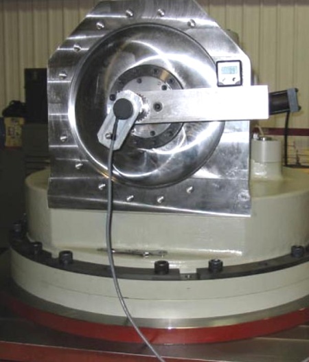
Ann Arbor, MI – The U.S. military has demanding requirements for the hardware it needs. Take, for instance, a set of gearboxes built by Excel Gear Inc., Roscoe, Ill, (excelgear.com) for missile launchers on the U.S. Navy’s new DDG1000 series of ships. The gearboxes are drive elements for the servo systems that rotate and elevate the missile launcher. For good servo performance the boxes must meet the Navy’s requirements for stiffness, efficiency, and low backlash.

QED 2A prototype was tested using a time consuming manual method. Although satisfactory, the method required careful checking to prevent data entry errors. Requirements for the test system called for high accuracy, elimination of measurement errors, and elimination of data entry errors. The company’s experience automating the test procedures provides a useful design lesson.

After successfully completing the prototypes, Excel Gear president N.K. Chinnusamy, decided the production run needed improved assembly procedures and to automate the test methods. Preload on the bearings was identified as an important factor – too little preload allowed excessive backlash while too much decreases efficiency and generates heat. A measurement accurate enough to size an optimum preload spacer is difficult because before the spacer is in place, the bearing can tip from side to side.

The company manufactured a set of fixtures to prevent bearing tipping and improve the repeatability of the preloads. The fixtures also improved the efficiency of the first production boxes and reduced their backlash from what had been attained in the prototype boxes.

Types of tests

The units called for several tests. For example:

Temperature tests during run-in: The primary sources of heat in the gearbox are seal friction, bearing friction, and oil churning. The heat generated by oil churning distributes throughout the box and dissipates through the case. Seal and bearing friction are concentrated and, if excessive, will cause failure. Temperatures are checked near the bearings on the high-speed shaft, where measurements on the prototype boxes showed the highest temperatures. These areas were also near the seals. Although it isn’t possible to separate the heat generated by the bearings and seals, the seals seem to generate the most heat.

Temperatures were recorded for two hours with the box running at maximum speed. After cooling, the test was repeated with the box running in the opposite direction. In the test, temperatures rose rapidly at first and then at a decreasing rate. While the temperatures do not reach equilibrium, in operation the boxes will not run continuously for two hours, and they will reach top speed only intermittently.

QED 4Gear-train stiffness: This characteristic, measured with the output shaft locked, was the ratio of the input-shaft motion to the torque applied, in Nm/rad. Torque was applied using a hydraulic actuator with two opposed cylinders driving two racks against a pinion. The racks are held in the pinion by a bushing. This results in friction force opposite to the direction of motion. Because the friction in the hydraulic actuator would cause measurement inaccuracies, the torque is measured between the actuator and the input shaft using a Dataflex 42/1000 torque transducer. This sensor has a capacity of 1,000 Nm in either direction. Torque is determined by measuring the twist in the transducer shaft using rotary encoders in a differential circuit. An encoder rotor is mounted at each end of the shaft. Because the encoder read heads are mounted to the stationary part of the transducer, there are no slip rings. The A-quad-B output from the transducer is converted to a voltage by an encoder electronic box. The voltage output range is 0 to 10V with a no load value of 5V, and the calibration constant is 0.200 Nm/mV.

Rotary motion was measured using a 2,000 line rotary encoder (resolution of 0.018° ). Because the input shaft extends through the box, the encoder is mounted on the opposite end of the shaft from the hydraulic actuator. When the box is in operation, a brake is mounted on this end of the shaft.

The A-quad-B output from the encoder is converted to a voltage by the programmable encoder-control box. The range and number of volts per degree can be set depending on the amount of rotation to be measured. The output has a range of 0 to10V. For this test, the output was 8.100° per V and the no-rotation voltage was 5V.

Gear train backlash: Some backlash is necessary to provide running clearance for the gears. Too little backlash results in overheating and premature failure, and too much degrades servo performance. Backlash is determined from the data collected for gear train stiffness.

Breakaway torque: For these boxes, it was low and measured manually using a snap-torque wrench. Although automated tests are usually preferred, a few are so simple that the programming required is not justified. This test, for instance, was the only one not automated.

QED 3Gearbox power losses over the full range of speeds: Input torque was measured with the gearbox running at a set of speeds both clockwise and counterclockwise. The torque is a nearly linear function of speed with a small component of stiction. This is preferred in a servo system because it contributes to servo loop damping. Because the torque is nearly a linear function of speed, the power-loss curve is nearly parabolic.

Test equipment

Accompanying images show the test equipment and The test hardware table lists a few of its details. The software used, DASYlab, is a graphical programming language. It is programmed by placing block diagrams representing data collection operations on a screen and connecting them with “wires” to control data flow. In the system used here, processed data is written to disk in a tab-separated format suitable for further analysis using Microsoft Excel.

Programming the data collection: The DASYlab block diagram provides an example programming screen. Each block represents an operation on the data such as collecting, scaling, saving to disk, and displaying. This programming method is faster than writing code. For example, the voltage output from the torque transducer, encoder, and thermocouples was connected to the electronic interface box. This box has a built in reference junction for the thermocouples. The device also has digital and analog outputs but these were not used. The interface box scans its inputs and converts from analog to digital values. These are passed to the computer through a USB connection at about 1Hz. This is relatively slow for data acquisition, but more than adequate for these quasistatic tests.

In the DASYlab program, the first box is an input box that “talks” to the hardware and places the input values on its outputs in digital form. Typically this is a special module that works only with particular hardware. Most other boxes do not depend on the type of hardware in the system. The other boxes used are numerical displays, graphical displays, and output boxes to record the data on disk. These boxes have corresponding components on a display screen. This screen can be a virtual instrument, that is, it can look like instruments such as voltmeters, oscilloscopes, and chart recorders. For this test the program converts the inputs to engineering units and displays the values several ways. Digital displays show the current numerical values of inputs.

Another display, an XY-plot, shows rotation on the Y-axis and torque on the X-axis. This feedback gives a preview of results. It can save much time because if something is wrong, such as a broken wire or failed thermocouple, it quickly becomes apparent. The test can be stopped, the problem corrected, and the test resumed. A problem that goes undetected until the data is analyzed wastes the entire test period.

A disadvantage of DASYlab is that this program had to be written with the computer attached to the interface hardware. It would be a great advantage to write the program sitting in front of a desktop computer rather than working in the test area using a laptop.

Details of the analysis

QED 1Backlash and Compliance: One advantage of automated data collection is the larger amount of accurate information than can be manually collected in a reasonable period. The additional data gives a better picture of the equipment characteristics than would otherwise be possible. In Backlash and compliance, the red line simulates points collected when the torque was varied from zero to maximum, to minimum, and back to zero three times. (The data shown are not actual values but they are an accurate representation of the type of data collected.) The data showed good consistency and repeatability, which produces confidence in the results. For instance, the blue line shows the curve fitted to the backlash and compliance data. The length of the vertical line at zero-load is reported as backlash. The slope of the lines fitted to the observations is the stiffness. This is a conservative method for determining such values. The normal manual four-point test would have given both lower backlash and compliance numbers. The four-point test uses two torques that are just a little higher than breakaway torque in each direction and two torques that are a quarter to one half of the full load torque.

Converting from manual to automated testing: The first use of an automated system involves debugging because the test system, as well as the tested device, may have problems. An advantage to starting this system was that previous manually collected results were available for reference. Problems with the test system are seen quickly. For the first test, some manual measuring devices were used in parallel with the new test equipment. This either verified the results or showed problems. For example, an incorrect scaling factor was quickly detected and corrected. This illustrates one principle of successful testing: Check the calibration of the test equipment before running the tests.

Peerless Precision in Remote Measurements

August 28, 2009 by admin  
Filed under Featured, Machine Vision/Inspection

By combining the best of two different distance measurement approaches with a super-accurate technology called an optical frequency comb, researchers at the National Institute of Standards and Technology (NIST) have built a laser ranging system that can pinpoint multiple objects with nanometer precision over distances up to 100 kilometers. The novel LIDAR (“light detection and ranging”) system could have applications from precision manufacturing lines on Earth to maintaining networks of satellites in perfect formation, creating a giant space-based platform to search for new planets.

LIDAR transmits light through the air and analyzes the weak reflected signal to measure the distance, or range, to the target. NIST’s new LIDAR, described in Nature Photonics,* has a unique combination of capabilities, including precision, rapid updates from multiple reference points at the same time, and minimal “measurement ambiguity.” The system can update measurements to multiple targets simultaneously every 200 microseconds. Measurement ambiguity in a LIDAR system is due to the fact that, if the target is at long range from the instrument, the system can’t distinguish between two different distances that are multiples of its “ambiguity range.” The new NIST LIDAR has a comfortably large ambiguity range of at least 1.5 meters—large enough to check the coarse distance with widely available technologies such as GPS.

No other ranging system offers this combination of features, according to the new paper. NIST’s LIDAR could enable multiple satellites to maintain tight spacing and pointing while flying in precision formations, acting as a single research instrument in space, the paper states. Formation flying has been proposed as a means to enhance searches for extraterrestrial planets, enable imaging of black holes with multiple X-ray telescopes on different satellites, and support tests of general relativity through measurements of satellite spacing in a gravitational field. The new LIDAR could enable continuous comparisons and feedback of distances to multiple reference points on multiple satellites. There also may be applications in automated manufacturing, where many parts need to fit together with tight tolerances, according to Nate Newbury, the principal investigator.

NIST’s LIDAR design derives its power from combining the best of two different approaches to absolute distance measurements: the time-of-flight method, which offers a large ambiguity range, and interferometry, which is ultraprecise. The LIDAR relies on a pair of optical frequency combs, tools for precisely measuring different colors (or frequencies) of light. The frequency combs used in the LIDAR are based on ultrafast-pulsed fiber lasers, which are potentially smaller and more portable than typical combs that generate laser light from crystals. The two combs operate at slightly different numbers of pulses per second. Pulses from one comb are reflected from a moving target and a stationary reference plane. The second comb serves as precise timer to measure the delay between the reflections returning from the target and from the reference plane. A computer calculates the distance between the target and the reference plane by multiplying the time delay by the speed of light.

Capacitive Motor Feedback System

August 28, 2009 by admin  
Filed under Featured, New Articles

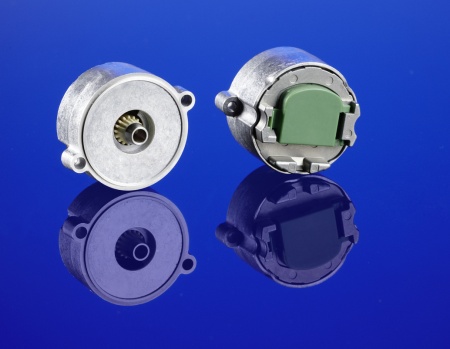
DAYTON, OH – SICK STEGMANN, INC. introduces SEK/SEL37 Capacitive Motor Feedback Systems. Just 36mm in diameter, these compact motor feedback systems with HIPERFACE® interface are available in singleturn and multiturn versions with a radial or axial plug outlet. The capacitive principle of operation is not only very accurate but also extremely robust, requiring no ball bearings. As a result, SEK/SEL37 motor feedback systems offer temperature resistance previously only found in resolvers.

Sick article 1

As is common with ultra-compact motor feedback systems, SEK/SEL37 motor feedback systems are designed for mounting directly onto tapered shafts. Holistic scanning almost fully compensates for eccentricity errors, with possible error sources having been practically eliminated by removing wear and tear parts. The SEK/SEL37 provide 16 sine/cosine periods, resolution of 512 steps per revolution, and 1 (singleturn) or 4096 (multiturn) steps per rev. They are rated for shock resistance to 100 g/10 ms, vibration resistance to 50 g/10 … 2000 Hz, and provide reliable operation in temperatures ranging from -40…+115°C (singleturn) or -20 …+115°C (multiturn).

SICK-STEGMANN-SEK_SEL37-Capacitive-Motor2.jpg

SEK/SEL37 capacitive motor feedback systems are an ideal alternative in applications currently using resolvers, but where users need higher performance, final positioning such as servo motors, handling drives, feed axis or standard robot applications. They are also well suited for use in traditional motor feedback applications that demand higher than normal robustness for reliable operation in high temperature and vibration environments common in textile machinery and mining applications, for example.

The multiturn properties of the SEL versions are implemented using a mechanical gearbox in combination with magnets and Hall sensors, achieving absolute, non-volatile code and position determination. A crucial advantage over resolvers is that no external evaluation unit is required – all electronics are contained within an integrated ASIC.

Thanks to HIPERFACE, all popular servodrives have an interface standard that covers all applications needing only one type of signal line. Another advantage is the possibility of self-initialization and automatic controller parametrization of the drive system by using an electronic type label, as with the SEK/SEL motor feedback systems. Motor characteristics, serial and part numbers as well as further data which quickly help in case of service or exchange are written here. These can be used to independently adjust the controller to the parameters of the motor.

HIPERFACE is an eight wire interface standard that makes it possible to get commutation, speed regulation and position information from a single device. The physical interface includes two wires for an RS485 link, four wires for sine & cosine signals and two wires for the power supply; a reduction from as many as 19 leads in a traditional system.

HIPERFACE compatible motor feedback systems combine the functions of both incremental and absolute encoders. The absolute value in these systems is calculated when the device is initially turned on, and is then transmitted via the RS-485 interface to a counter in the drive. The drive uses this initial absolute value for the commutation of the motor and also as a pointer to identify the exact period of the sine/cosine signals that the drive is currently evaluating. The drive then increases the base resolution of the sine/cosine signal by interpolating these signals in the drive with an A/D converter.