Handheld Laser Light Source

September 14, 2009 by admin  
Filed under New Articles

Toronto, Canada – GAO Instruments has launched its durable, compact fiber optic laser light source for use in the field or lab applications. It performs fast and accurate measurement on long-distance and local optical networks.

Handheld

This portable laser light source, model A0630010, offers high stability for accurate fiber optic testing. It provides stable power output at a wavelength of 1310nm or 1550nm through a single output connector. The light source can operate in either continuous wave mode or 2kHz modulated mode for up to twelve hours without any service interruption. It can measure the loss in an optical fiber up to 200km in length with high accuracy. The device also gives a low battery indication when requiring battery replacement.

Handheld ADSL 2+ Tester Provides Increased Performance

September 14, 2009 by admin  
Filed under PC-based Test Equipment

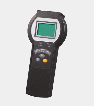
Toronto, Canada – GAO Instruments offers its compact, handheld and easy-to-use test instrument – ADSL 2+ Tester, which is used to test ADSL, ADSL2, ADSL 2+ and RE-ADSL2 lines. This multi-functional tester quickly determines whether the line tested complies with appropriate standards and clearly displays test results through its high resolution, backlit LCD, and indicates alarms and the connectivity of WAN or LAN.

Handheld

This ADSL 2+ tester, model A0300010, conducts ADSL2+ line parameter testing, TX and RX data packet accounting, PING testing and ISP login simulation. The tester writes VPI, VCI, user name and password automatically according to embedded configuration parameters and also allows the input of configuration and margin values via Test Manager Pro software. It supports a maximum measurement distance of 6.5km and is able to store over one hundred test results; test results can be downloaded to a PC for further analysis, printing, and output. Configurations and margins can also be saved and downloaded through its software interface.

GAO Instruments also offers a series of ADSL testers for customers to choose from.

Data Acquisition Card Upgrade
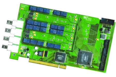
September 14, 2009 by admin  
Filed under Data Acquisition, Featured

Toronto, CanadaGAO Instruments recommends its upgrade data acquisition product, the PCI4712 parallel data acquisition card. This four-channel and single-ended card features a 12-bit analog-to-digital converter (ADC) and four independent programmable amplifiers. It has been widely used for transient signal recording, refined frequency synthesis, multi-channel parallel acquisition systems and time-phase-sensitive acquisition. The data acquisition card with high speed is ideally suited for the formation of long-based, multi-channel virtual instrument systems.

Data Acquisition articleThis A0720005 parallel data acquisition card from GAO Instruments uses advanced technology and processes, and independent A/D for each channel, amplifier and buffer, thus making the product features synchrony expansion of multi-card, high-speed parallel acquisition, large-capacity cache, small phase difference, high precision. It offers a maximum sampling rate of 50Msps and refined sampling rates from 100sps to 50Msps. The high resolution card supports all-electronic calibration – there are no POTs on the card to adjust. Remote ynamic upgrade service and voltage signal acquisition range from 100mV to 20V; the maximum sampling depth of each channel is up to 16M.
This PCM4712 parallel data acquisition board is one of the GAO Instruments’ popular line of PCI cquisition boards.

Optical Testing Device from Yokogawa

September 14, 2009 by admin  
Filed under Bench Test, Machine Vision/Inspection

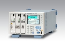
Yokogawa has released the AQ2200 multi-application test system, designed for measuring and evaluating a wide range of optical devices and optical transmitters.

The AQ2211 and AQ2212 frame controllers are central to the system and incorporate a variety of measurement functions and applications.

Yokogawa

According to the company, remote monitoring and measurement is available via the included USB, Ethernet or GP-IB ports. A macro programming function allows users to build up auto-measurements systems, available for call up at any time.

Remote viewer software for controlling frames and modules is also included.

A variety of measurement modules are available, including: high-stability light sources, wideband tunable light sources, high-speed optical sensors with low PDL and high-resolution variable optical attenuators.

Measurement modules can be inserted or removed without turning off the power.

Danaher Test and Measurement Supplier of the Year

September 8, 2009 by admin  
Filed under New Articles

Multek, a wholly-owned subsidiary of Flextronics announced that it has been recognized by Danaher Test and Measurement as its 2009 outstanding supplier of the year. Multek was chosen based on criteria including quality, delivery performance, engineering support and cost for its work with two of Danaher Test and Measurement’s business units, Tektronix and Fluke. Multek supplies printed circuit boards for Tektronix and Fluke products as well as LCD displays for Fluke products.

“Multek has consistently provided superior value and technical support for the Test and Measurement business,” said Jeff Jones, director of Tektronix commodity management. “Their technical innovation, quality culture and flexible business solutions are a role model of supplier excellence.”

“We are very pleased with this recognition and would like to thank the team at Danaher for honoring us with this award,” said Werner Widmann, chief executive officer and president of Multek. “The team at Multek is completely committed to providing the highest quality, most reliable PCB manufacturing solutions to customers worldwide. This recognition underscores our dedication to serving Danaher, as well as our other customers, and to providing leading edge products that improve the competitiveness of our customers.”

Multek was honored with the award at Danaher’s 2009 annual supplier symposium, which took place in Everett, Washington last month.

Fluke Ti32 Industrial-Commercial Thermal Imager

September 2, 2009 by admin  
Filed under Data Acquisition, New Articles

Fluke Corp., provider of handheld electronic test and measurement technology, introduced the Ti32 Thermal Imager, designed and priced to deliver what it believes is unprecedented performance for troubleshooting and preventive maintenance of electrical installations, electro-mechanical equipment, process equipment, HVAC/R equipment and more. In these tough economic times, these new imagers help its customers do that, the company says.

Fluke Ti32 is the first imager on the test and measurement market to incorporate a powerful 320×240 pixel sensor to provide strikingly crisp, detailed images for under $9,000, the company says. Using its patented IR-Fusion technology, users can marry high-precision thermal images with visual (visible light) images in full screen, picture-in-picture, or blended views for enhanced problem detection and analysis.

Fluke claims that its IR-Fusion is the only solution available with physical parallax correction, which enables perfect alignment, pixel by pixel, of both infrared and visible images. Fluke products are the only thermal imagers on the market to incorporate IR-Fusion in the camera and software.

The Ti32 is designed to make thermal imaging affordable and effective in many applications for plant maintenance professionals, production engineers, electricians, HVAC/R technicians, and others. Users can record voice comments with every image taken. It includes a three-button menu designed for intuitive operation and navigation, on-screen emissivity correction, transmission correction, and high temperature alarm.

Fluke Ti32 Thermal Imager, motor

Fluke says that the combined capabilities of its Ti32 can help plant and system maintenance professionals reduce energy consumption, strengthen preventive maintenance programs, and increase reliability by expanding problem detection, and providing customized reports.

Each unit comes with two field-swappable, rechargeable batteries that enable virtually continuous imager use. Typical battery life is more than four hours each. Optional telephoto and wide-angle lenses are available to bring distant and wide views into sharp focus.

The device is tested to withstand a drop of 6.5 ft. (2 m), and is IP54 rated to withstand water and dust. With a widescreen, full color LCD display, increased thermal sensitivity (≤0.05 °C at 30 °C target temperature) and a temperature measurement range of -20 to +600 °C (-4 to +1112 °F).

Fluke SmartView software (with free software upgrades for the life of the product) is included with each thermal imager. SmartView software is a modular suite of tools for viewing, annotating, editing, and analyzing infrared images that fully supports IR Fusion technology. It enables users to edit images in five viewing modes and generate customized professional reports in a few steps. Fluke 3D-IRM three-dimensional viewing makes hot or cold spots “pop out” of the background for easy viewing and analysis.

The Ti32 includes a 2 GB SD memory card that will store at least 3,000 basic infrared images (.bmp or .jpg formats) or 1,200 fully radiometric (.is2 IR Fusion file format) infrared and linked visual images, each with 60 seconds of voice annotation, as well as a multi-function memory card reader (USB) for downloading images into a computer.

Fluke Ti32 Thermal Imager can check motor components.

Each imager comes with a hard carrying case and soft transport bag, an adjustable hand strap for right- or left-handed use, two rechargeable lithium ion smart batteries, a two-bay external charger, an ac power supply, and an interactive training DVD.

The imager is designed for inspection and process control applications in many industrial functions, including:

• Inside electrical distribution and service, including switch gear, panels, controls, fuses, transformers, outlets, lighting, conductors, overhead buss, motor control centers, and other equipment:

• Motors, pumps and mechanical equipment, such as electric motors and generators, pumps, compressors, evaporators, bearings, couplings, gearboxes, gaskets/seals, belts, rollers, and other equipment;

• Process tanks and vessels, pipes, valves and traps, reactors and refractory insulation;

• Air conditioning, heating, air handlers, compressors, chillers, boilers, furnaces and refrigeration; and

• Outside electrical distribution, transformers, bushings, insulators, transmission lines, large circuit breakers, service connections, disconnects, capacitor banks, and other equipment.

IR-Fusion technology

Fluke says its IR-Fusion technology captures infrared and visible light images and simultaneously displays the images fused together, adding a new dimension of detail that saves time and best conveys infrared information of each specific application and environment. It features multiple viewing modes and allows users to manipulate images on the camera’s display. By enabling users to manage and analyze images with complete control over both the infrared and visible light spectrums, IR-Fusion makes it easier to identify details and potential problems.

Broadband Across America from JDSU

September 2, 2009 by admin  
Filed under Featured, PC-based Test Equipment

MILPITAS, CA – JDSU launched “Broadband@Work Across America,” a campaign to help raise
awareness and educate rural service providers on the technical issues and
challenges that could impact their ability to successfully deploy broadband
services in towns across the country.

JDSU Test and Measurement 1

The campaign is inspired by the 2009 American Recovery and Reinvestment Act,
which provides $7.2 billion to accelerate broadband service deployment to
rural and under-served regions in the nation. The first deadline for broadband
stimulus grant applications was recently completed on August 20, 2009, and two
more will be scheduled until all funding is awarded on September 30, 2010.

Broadband@Work Across America leverages JDSU’s decades of expertise in
broadband network test and management solutions as well as optical components
and equipment, to help rural telecommunications providers use stimulus funds
to deploy broadband services through fiber-to-the-home (FTTH), digital
subscriber line (DSL), wireless, and hybrid fiber-coaxial (HFC) systems, among
others.

JDSU Test and Measurement

JDSU’s Broadband@Work Across America campaign will be featured at OSP Expo
2009 in Minneapolis, September 2-3, booth #508. JDSU will be exhibiting its
leading broadband test and measurement solutions and displaying the new
campaign theme, literature, special offers, giveaways and other supporting
materials.

“With proper testing, rural telecommunications providers can avoid facing
technical issues in their broadband deployments that cost time and money,”
said Dave Holly, president of JDSU’s Communications Test and Measurement
business segment. “JDSU’s Broadband@Work Across America campaign offers
information, training and solutions to help providers deploy broadband
services as quickly as possible.”

Source Measure Unit from Agilent Technologies, Inc.

SANTA CLARA, CA – Agilent Technologies Inc. introduced a three-channel source
measure unit (SMU) that can simultaneously provide power and perform
measurements in applications such as parametric testing of diodes, LEDs, CMOS
integrated circuits and other semiconductor devices. The U2723A USB modular
SMU`s compact size saves benchtop space, and its improved throughput saves time.
It is the latest addition to Agilent`s family of paperback-sized USB modular
instruments.

Agilent SMU

The compact U2723A, which supplies voltage (± 20 V) and current (120 mA) on all
three channels, can operate in four-quadrant mode and also provides accurate
current measurements down to nanoamp levels. With 15 ms rise time, the SMU
improves throughput, especially during mass testing of semiconductor devices. It
also simplifies automated testing with up to two embedded test scripts per
channel.

The Agilent U2723A can be used as a standalone instrument or as a module plugged
into the compact U2781A USB modular-products chassis. For standalone use, the
U2723A can be connected to a PC via USB, and testing can be performed with the
bundled Agilent Measurement Manager (AMM) software. To simplify integration into
new or existing test systems, AMM includes a code-conversion capability that
translates commands into forms compatible with popular programming languages
such as C#, C++, Agilent VEE and Microsoft® Visual Basic.

Testing Provides Roadmap to Intelligent Assembly

September 2, 2009 by admin  
Filed under Featured, Machine Vision/Inspection, New Articles

“Intelligent assembly” is an approach to quality that shifts the focus from ever-tighter dimensional tolerances to consistent function in the final assembly. It’s based on the use of servo devices and sensors to monitor the assembly operation in real-time, and computer software to determine when the product meets acceptable functional parameters.

Proponents of Intelligent Assembly claim that many components and products could be produced at lower cost with no sacrifice in performance by simply changing the way quality is defined, and adopting intelligent assembly systems. But, the necessary systems aren’t exactly staple items on the shelf of every supplier and that has been one of the factors keeping intelligent assembly from more widespread adoption.

There’s a bit of folk wisdom that says, if the only tool you have is a hammer, it doesn’t take long for everything to start looking like a nail. Since at least the 70’s, manufacturers have been doggedly pursuing “quality” improvements with the only tool available, tighter and tighter tolerances.

Promess.press.relese.1.gif

Fig. 1-New Promess integrated torque functional test TFT 1/200 is rated at 1 N-m (9 in.-lb) with a maximum rotational speed of 200 RPM in either direction.  TFT systems are used by test equipment builders and end users in a broad range of testing and measuring of torque applications, including automotive steering and drive train component testing and assembly, manual window crank final testing, seat testing, bearing pre-load, and torque-to-turn testing.

But adding extra zeros to a tolerance specification, also adds extra zeros to production costs, and there are limits to how much consumers will pay for “quality” achieved that way. Perhaps it’s time to stop looking for perfection, and start looking for some new tools.

Intelligent assembly systems
An intelligent assembly system gives you a whole new toolbox. Intelligent Assembly is based on the idea that function is the consumer’s ultimate measure of quality. Under that definition it doesn’t matter if the components are perfect, as long as they work properly and deliver acceptable value to the user.

If the assembly system is smart enough to tell the difference between good products and bad products as they are being made, then it’s quite possible to loosen tolerances in the supply chain – or at least stop tightening them. That can be done today using a combination of servo-controlled, instrumented assembly equipment, and sophisticated, real-time computer analysis of the process data.

Custom-engineered Intelligent Assembly systems have been available for more than 20 years. Some use a technology called “signature analysis” to monitor and qualify the assembly process.

What this means is that the assembly system records the force/distance, force/rotation, force/time or other critical relationships of a known good assembly to create a profile or “signature” of the process that produced it. By comparing each subsequent operation to the “signature,” and setting upper and lower tolerance limits, production of good functions or tolerances can be assured without the need for subsequent inspection.

The signature is typically represented as a pair of curves on the system’s display. As long as the results of any individual assembly operation fall within the area between the two curves, the product can be expected to perform as specified.

The exact shape of the signature also provides information about the individual parts being assembled, which can be used as input to control strategies for other processes. For example, parts that are too soft or too hard will produce a distinct change in the signature, as will parts with out-of-tolerance assembly details such as hole or shaft diameters.

The technology has been applied in hundreds of different applications ranging from automotive hood latches, to medical catheters, and including many items traditionally thought of as requiring extremely tight dimensional tolerances.

In the hood latch application, for example, the assembly system cycled the latch while the rivet holding it together was peened. It stopped the peening process when the force required to move the latch reached a specified value. That way, all of the latches produced functioned identically, despite wide variations in rivet dimensions and properties.

Medical catheters have a small diameter metal tube crimped to a larger tube that’s attached to the flexible portion of the catheter. If the crimp fails, the catheter either comes apart or closes off, both of which are unacceptable.

A hydraulic press previously used for the crimping operation produced inconsistent results. It was replaced by an Intelligent Assembly system that provides a 100% effort test certification for every catheter produced, and virtually eliminates crimp failures in the field.

Promess builds Intelligent Assembly systems based on a line of proprietary servo-controlled electromechanical presses; a series of precision torque units; and a line of computer-based controls running Windows(tm)-based software. Other suppliers use similar products, most of which are proprietary as well. Until recently, that meant that anyone wanting to use Intelligent Assembly technology was essentially limited to a custom-engineered system.

Assembly components
The situation is changing, though, as the components required to build intelligent assembly systems become standard, and readily available to end users who want to experiment with the technology before committing to it. Promess, for example, in recent years has made a number of individual components available to customers who wanted to build their own systems. These include a small (1 Nm) torque functional test (TFT) integrated torque-monitoring-and-control systems, Fig 1, and a line of customizable servo-press workstations intended to offer a semi-standard solution for high-precision assembly and test applications, Fig. 2.

Promess_workstation.gif
Fig. 2-New customizable servo-press workstations offer a semi-standard solution for high-precision assembly and test applications, based on Promess’ electromechanical assembly press (EMAP), intelligent control, and integrated sensor technologies. Typical applications include assembly and testing of springs, check valves, anti-lock brake components, shock absorbers, oxygen sensors, and a broad range of fluid measurements.

The new TFT 1/200 is rated at 1 Nm (9 in.-lb) with a maximum rotational speed of 200 RPM in either direction. Each system consists of a torque module containing a servomotor, encoder, torque transducer, and output shaft plus a Promess EMAC electronic controller/monitor.

The torque module can produce output rotation in either direction, and the integral angular encoder provides shaft-angle feedback to the control. Mechanical overload stops to protect the transducer. The TFT replaces the traditional inline motor/transducer torque-sensing system with a single, fully integrated unit.

The workstations are based on the field-proven Electro-Mechanical Assembly Press (EMAP), with intelligent control, and integrated sensor technologies integrated with Windows-based, icon-driven software. They provide a custom foundation for sophisticated assembly and test systems.

The EMAP, which is also available as a component, consists of a ball-screw driven by a servomotor and equipped with an array of force and position sensors. The unit provides precise monitoring and control of force and position during assembly and test operations. Because the EMAP is servo-driven, the entire system is easily programmed either on or off-line, and easily reconfigured to handle a variety of different parts and/or operations.

Standard workstations are available with press capacities ranging from 40 kN to 120 kN, with larger and smaller sizes available as special orders. Both press to force/position and pull-to-force/position operations are possible with the Promess servo-press workstation. Typical applications include assembly and testing of springs, check valves, antilock brake components, shock absorbers, oxygen sensors, and a broad range of fluid measurements.

Both the TFT and the workstation used the Promess Electro-Mechanical Multiaxis Controller (EMAC). This is an easily programmed, fully integrated, multiaxis motion controller and data-acquisition-and-analysis system that performs the analytical functions using Promess-developed software.

These capabilities deliver the final piece of the intelligent assembly system, providing real-time monitoring and analysis using signature analysis technology. In simple terms, the system records the force/position signature of a known good operation, and then compares subsequent operations to it. The net result is that ability to replicate known good assemblies or processes.

None of this is earthshaking news to those who have been following the development of intelligent assembly technology, but the fact that the necessary components are now available as stand-alone products is something relatively new. The upshot is that these systems are now within reach of more potential users who don’t need a custom-engineered solution, but who can still benefit from the technology.

Promess, Inc.

Test and Measurement Basics of Microphones

September 2, 2009 by admin  
Filed under Communication Test, Featured


Microphones are familiar sensors that transform sound pressure waves into electrical signals over a broad range of frequencies and amplitudes. They are an integral part of a variety of devices including tape recorders, hearing aids, telephones, and computers. They are also used in radio and television broadcasting and audio engineering. But another specific class, perhaps not as well known, is intended for the scientific measurement of certain types of sounds and noise levels, including ultrasound. Sounds monitored for test and measurement purposes are recorded, analyzed, and typically assigned somewhat different quantitative and qualitative values than voice and music in the entertainment industry. The most common types of microphones include carbon, magnetic, piezoelectric, and condenser.

Figure1_MicComponents.jpg
Condenser microphones have a simple construction. As sound waves vibrate the diaphragm, the spacing, and consequently the capacitance, between it and the back plate varies. The varying capacitance, in turn, generates a fluctuating electrical signal that is amplified and otherwise processed, depending on the instrumentations’ needs.

Each type is best suited for a specific application. For example, carbon microphones were first used in telephones and for radio communications. They are relatively low-cost, rugged, two-terminal devices that contain a small cartridge of lightly packed carbon granules, usually biased with current or voltage. When acoustical pressure waves hit the microphone, the carbon granules compact and relax thus modulating the terminal resistance. The continuously changing resistance then generates an output signal of varying voltage or current in step with the sound pressure waves at the microphone’s input.

Magnetic microphones are dynamic transducers that contain a moving coil, and are based on the principal of magnetic induction. Here, a coil of wire attaches to a lightweight diaphragm, which is in the presence of a magnetic field. The coil moves and generates a voltage proportional to the applied acoustical pressure.

The third type, a piezoelectric microphone, uses either a natural quartz or manmade ceramic crystal. Although these microphones have relatively low sensitivity levels, they are durable and can measure high amplitude pressures. Conversely, their noise-floor level is generally high, which make them particularly suitable for shock and explosive-type pressure measurements.

Condenser microphones come in two types, externally polarized, and pre-polarized. They transform the sound pressure waves into capacitance variations, which are then converted to electrical signals. The unit’s cartridge comprises a small thin diaphragm spatially in parallel with, but not electrically contacting a stationary metal back plate connected to a voltage source. In the presence of oscillating pressure, the diaphragm moves and changes the gap between the diaphragm and the back plate. This produces an oscillating voltage output, which is proportional to the original pressure signal.

Figure2_FreeField.jpg
Free-field microphones are intended to pick up sound waves from a single source. They are calibrated to compensate for any sound-wave diffraction that might affect the sound pressure at high frequencies. The microphone’s presence in the field does not affect the measurements.

The voltage source for an externally powered condenser microphone is usually a 48 to 200 V power supply. By comparison, a newer pre-polarized microphone has an “electret” layer of charged particles deposited on its backplane to supply the polarization. The electret microphone can use inexpensive constant-current supplies instead of costly polarized power supplies. Also, more economical BNC coaxial cables or 10-32 connectors can be used instead of the LEMO-type, 7-pin connectors and cables. Coaxial cables can carry the signals over long distances without significant degradation. Modern pre-polarized microphones are becoming the preferred type for laboratory test, measurement, and field applications.

Selecting and specifying microphones
Most types of microphones can measure broadband sound pressure levels from a variety of sources, but high-precision condenser microphones characterize the sound better than most. When choosing the optimum microphone, a number of factors must be considered:  the application, the sound source, and the operating environment. Also, investigate the type of response (application) field, dynamic response, frequency response, polarization type, sensitivity required, and temperature range needed. A variety of condenser microphones are available for specific applications.

Precision condenser microphones work well in three common application fields: free-field, pressure-field, and random-incident (diffuse) field. Free-field microphones are intended for measuring sound pressure variations that radiate freely through a continuous medium, such as air, from a single source without any interference. The microphone is typically pointed directly at the sound source (0º incidence angle). Free-field microphones measure the sound pressure at the diaphragm; however, the sound pressure may be altered from the true value when the wavelength of a particular frequency approaches the dimensions of the microphone. Consequently, correction factors are usually added to the microphone’s calibration curves to compensate for any changes in pressure at its diaphragm due to its own presence in the pressure field. These microphones work best in anechoic chambers or large open areas where hard or reflective surfaces are absent.

The second type is called a pressure-field microphone. They measure sounds from a single source within a pressure field that has the same magnitude and phase at any location. In order to simulate a uniform pressure field, they are usually calibrated in enclosures or cavities, which are small compared to their wavelength. This minimizes any alterations in measurements due to the presence of the microphone in the sound field. They are also supplied with a pressure versus frequency-response curve. Such microphones measure the pressure exerted on walls, airplane wings, or inside structures such as tubes, housings, and cavities.

Figure3_Pressure_Field.jpg
A pressure-field microphone is intended to measure sound pressure in a field that has the same magnitude and phase at any location within it. Unlike the free-field microphone, its presence in the field does affect the measurement, however this effect is typically compensated in its design.

The third type is called a random-incident or a diffuse-field microphone. They are omni-directional and measure sound pressure from multiple directions and sources, including reflections. They come with typical frequency response curves for different angles of incidence and compensate for the effect of their own presence in the field. An appropriate application for this type of microphone is measuring sound in a building with hard, reflective walls, such as a church.

Figure4_RandomIncidentField.jpg
Random incident microphones are not as common as the other types. Few manufacturers rate them as such; since the small (0.5-in. diameter) pressure field microphones operate similarly, when equal-pressure sound waves hit the microphone from all directions.

Dynamic response
The main criterion that describes sound is based upon the amplitude of sound-pressure fluctuations. The lowest amplitude that a healthy human ear can detect is 20 millionths of a Pascal (20µPa). Since the pressure numbers represented by Pascals are generally extremely small and not easily managed, another scale is more commonly used, called the decibel (dB). This scale is logarithmic and more closely matches the response of the human ear to pressure fluctuations. Some examples of typical sound pressure levels used as a reference include the following:

chart2.jpg
Table of Sound Sources and Their dB Ratings

Typically, the maximum decibel level is based on the physical characteristics of the condenser microphone. The specified maximum dB level refers to the point where the diaphragm approaches the back plate, or where total harmonic distortion (THD) reaches a specified amount, about 3% or less. The maximum level in dB that a microphone outputs in a certain application depends on the voltage supplied and its sensitivity. In order to calculate the maximum output for a microphone, use a specific preamplifier and its corresponding peak voltage, and then calculate the pressure in Pascals that the microphone can accept. The amount of pressure is determined from the following equation:

eq1.gif

Where: P = Pascals, Pa
Voltage = the preamps output peak voltage, V.

After the maximum pressure level that the microphone can sense at its peak voltage is determined, it can then be converted to dB using the following logarithmic scale:

eq2.gif

Where: P = Pressure in Pascals, Pa
Po = Reference Pascals, Pa (Constant = 0.00002 Pa)

The microphone’s cartridge thermal noise (CTN) rating indicates the lowest measurable sound pressure level that it can detect above the electrical noise inherent within the microphone. The inherent noise level of a microphone and preamplifier combination is highest at both the lower and upper limits of the microphone. Each microphone has a unique noise characteristic, and the diameter of the microphone strongly influences its frequency response and noise level.

Frequency response
After the microphone’s field response and dynamic range have been determined, find the usable frequency range from its specification sheet. Proper selection requires that the measured pressure levels fall between the microphone’s low-end noise level (CTN), and the maximum rated dB level of the microphone. In general, the smaller the microphone diameter, the greater the high-end dB level expected. The larger diameter microphones are recommended for lower frequency range amplitude (dB) measurements since the inherent noise or CTN specifications are typically lower.

Manufacturers typically specify a ± 2 dB tolerance on the frequency versus output amplitude. When comparing microphones, check the tolerance in the specific frequency range most needed. When an application is not critical, select a wider frequency range with a higher allowable output (dB) tolerance from the manufacturer’s specification sheet.

Polarization type
Condenser microphones are further classified in two categories; traditional externally polarized and pre-polarized microphones. Either type works well for most applications, but the pre-polarized units tend to produce more repeatable output in humid surroundings. Pre-polarized microphones are recommended where temperature changes can promote condensation and short circuits on the internal components of externally polarized microphones. Conversely, at temperatures between 120 and 150º C, externally polarized microphones are better suited, because their sensitivity level is more consistent in this range.

Microphone sensitivity is inversely proportional to temperature. Microphones operated or stored in high temperature environments may require calibration more frequently. However, a probe microphone is specifically intended for withstanding these kinds of harsh environments. It combines a microphone with a probe-type extension tube for mounting close to the sound source. The probe tip contains the microphone, and the signal-conditioning module may be remotely located, either in a less harsh environment or where access to the sound source is too small for a typical condenser microphone.

Special applications
Microphones are often designed for special applications. For example, corrosion-resistant microphones called hydrophones are used for testing, monitoring, and measuring sounds under water. Different models are available for different sensitivities, frequencies, dB levels, and operating depths.

Another particular type, sound level meters, are special instruments intended to read sound pressure levels quickly and conveniently. Portable units are usually small, handheld instruments, which include the microphone, preamplifier, power source, software, and display. They measure ambient noise levels on the street and artillery ranges; in factories, power generating plants, shopping malls, office buildings, and numerous other places.

Intensity probes are usually the best choice for measuring the magnitude and direction of a sound. The set up usually consists of two phase-matched microphones with a spacer between them. They measure the pressure level as well as the speed and direction of the propagating sound waves. The higher frequencies typically require a smaller spacer, while larger spacers are used for lower frequencies or where sounds might reverberate.

Array microphones are used for near-field, acoustic holography (NAH). These are applications where 3D field values are studied. A number of array microphones are placed in a predetermined pattern and combined with appropriate software to map the acoustic energy flow of a complex sound pressure field. Array microphones work especially well where a large number of microphones are used concurrently. Also, Transducer Electronic Data Sheet (TEDS) are recommended to be used with arrays, since they let the user quickly and easily identify a particular microphone within the array. TEDS chips and firmware are typically stored electronically in each microphone and list its model number, serial number, calibration date, along with the specifications of the microphones sensitivity, capacitance, impedance, and other information that can be downloaded to help ensure accurate test results.

Figure8.gif
Array microphones are usually free-field types, and are intended to be a low-cost application for multiple channel sound measurements. For example, they are used in acoustic holography and pressure mapping such as vehicle testing to record the sound level at different points around an automobile engine, body, or tire well.

Finally, outdoor microphones can withstand rigorous environmental exposure, such as in airports and on highways. Noise measurements here are crucial to providing information for improving human safety conditions. Environmental and outdoor microphones provide different levels of protection for the internal components, while maintaining their high-accuracy specifications.

PCB Piezotronics Inc