Instron Introduces Universal Testing Machines

October 30, 2009 by admin  
Filed under Featured, Test Equipment

5900 Series Load Frames are built with robust ball screws, precision guidance columns, and dual-belt drive systems

5900 Series Load Frames are built with robust ball screws, precision guidance columns, and dual-belt drive systems

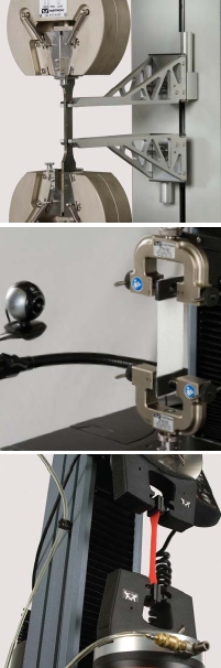
Instron, announced its new line of universal materials testing equipment.  The 5900 Series has improved ergonomics, accuarcy, and reliability as well as an enhanced overall experience for the operator.

The single column tabletop systems, with a small footprint ideal for lab use, are designed for low-force testing up to 2 kN. These systems are commonly used for medical devices and biomaterials, textiles, small components and electronics, food, paper, and plastic films. The dual column tabletop systems are ideal for mid-range testing. With testing capacities up to 50 kN, these multi-purpose tabletop instruments meet the requirements of a variety of industries, and are commonly used for plastics, metals, and rubber. The dual column floor model systems are built for high-capacity testing up to 600 kN. These robust, heavy-duty frames are ideal for demanding applications including testing of high-strength metals and alloys, advanced composites, aerospace and automotive structures, and more.

The servo-control and signal conditioning electronics are designed by Instron specifically for materials testing applications. Their proprietary load cell design allows us to control all facets of force measurement – the most critical aspect of mechanical testing. The cutting-edge load cell construction ensures that our systems achieve their maximum level of performance. Additionally, our significant investment in primary force calibration standards and a factory-based calibration laboratory allows us to offer capabilities normally found only in a National Standards laboratory.

5900 Series Load Frames are built with robust ball screws, precision guidance columns, and dual-belt drive systems, and are designed to provide higher stiffness and precise alignment for testing everything from medical devices to high-strength composites. The rigid mechanical design ensures the best possible conditions for repeatable test conditions and reliable results, and is the primary reason why Instron systems last for decades.

The 5900 Series operates on Bluehill 2 Software and a control panel that contains customizable soft keys and live displays that monitor real-time data from any two channels (e.g. load, extension, tensile stress). Tests can easily be run directly from the control panel, resulting in greater overall testing efficiency.

http://www.instron.us/

Tektronix Buys Sypris Solutions Business Segment

October 28, 2009 by admin  
Filed under New Articles, Test Equipment

Tektronix, Inc., a supplier of test, measurement, and monitoring products and solutions, completed the acquisition of the Test & Measurement business from Sypris Solutions, Inc. (Nasdaq/NM: SYPR ) for $39.0 million.

Sypris Test & Measurement, Inc. is a provider of calibration services, testing and component sourcing services, and specialty products.  The company serves in a variety of markets, including military, aerospace, avionics, telecommunications, automotive, semiconductor, medical and more.

Expanding multiple vendor service offerings to support customers through the entire product life cycle is a strategic initiative for Tektronix.  Sypris Test & Measurement brings a strong U.S. footprint of locations to provide rapid turn-around to customers across a wide range of parameters through on-site, mobile, or service offerings to current and future Tektronix customers.

http://www.tek.com/

http://www.sypris.com/

High Resolution Digitizer for Defense Markets

October 16, 2009 by admin  
Filed under Bench Test, Featured, New Articles

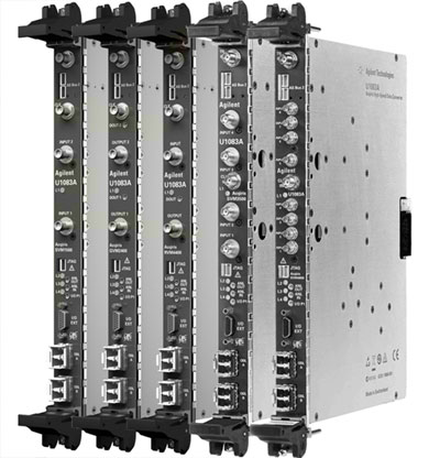
Agilent Technologies introduces its Acqiris product line’s highest-resolution VME/VXS digitizer. The SVM4800 is an eight-channel 14-bit digitizer with more than 300 MHz input signal bandwidth, achieving sampling of up to 125 MS/s. This new digitizer is ideal for applications in radar, Electronic Warfare (EW) and Synthetic Instrumentation (SI).High-Resolution-Digitizer's

The Agilent SVM4800 builds on the modular U1083A VME/VXS base card with an analog digitizer mezzanine that includes two DC-coupled 14-bit, 125 MS/s quad-ADCs. Agilent know-how in digitizer development combined with extensive use of state-of-the-art technology allow reaching outstanding analog performance, including spurious free dynamic range (SFDR) of up to 82 dBc, total harmonic distortion (THD) of 82 dBc, and signal to noise ratio (SNR) over 70 dBc, leading to an effective resolution of more than 11.2 bits (ENOB) at 125 MS/s. The mezzanine also includes a Xilinx Virtex-5 FPGA that provides data MUX function and static data gain and offset correction.

The base card provides high-performance, real-time data processing by means of two very large Xilinx Virtex- 4 FPGAs, one SX55 and one FX100. The board supports eight 3.125 Gbps serial links on the VXS backplane and two optical links on the front panel supporting up to 3.125 Gbps, providing a substantial aggregate data bandwidth of more than 3.5 GB/s. Its fully compliant VME64x interface supports the 2eSST protocol.

An optional firmware development kit (FDK) is available to help application firmware implementation on the SX55 and FX100 FPGAs. The FDK includes a set of cores to easily interface to the underlying hardware, a base design for each family member to provide very simple, ready-to-use designs, and a test-bench environment for design and simulation.

This product is intended benefit those charged with closing the gaps in emerging threats through new technology or by refreshment of fielded Electronic Support (ES), Electronic Attack (EA) and Electronic Counter Measure (ECM) systems, the majority of which are based on the ubiquitous VME architecture. Longer emitter identification standoff ranges, more precise direction finding in dense emitter environments, and shorter defensive engagement cycles are possible with relatively low incremental development cost. Wideband radar and intelligence-gathering systems are also expected to benefit, with better clutter rejection, range and target differentiation now attainable without massive reinvestment.

Optical Power Meter with Long Operating Time

October 16, 2009 by admin  
Filed under Meters & Testers

Optical-Meter
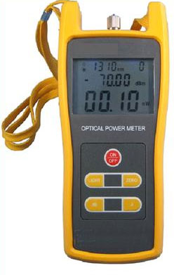
GAO Fiber Optics launched its upgraded, highly accurate optical power meter used for absolute optical power and relative loss measurements of fiber optics. This practical optical power meter features absolute and relative power measurements, a high accurate test precision of ±5% and an automatic self calibration function. It is an essential solution for telecom and CATV maintenance as well as fiber optics test labs.

This multi-functional power meter, model 08113, displays optical power in mw, dB and dBm on its large, high definition LCD screen. It supports 850, 1300, 1310, 1550 and 1490nm calibrated wavelength and provides optional FC, SC and ST interchangeable connectors. This easy-to-use optical power meter is resistant to dust and water which makes it suitable for use in any harsh environment. It supports more than 240 hours continuous operation using three 1.5V batteries and consumes little power due to its auto-off function. The rugged power meter is ideal for use in the field as it is light in weight and compact in size.

GAOFiberOptics

Handheld Spectrolightmeter

October 16, 2009 by admin  
Filed under Data Acquisition, Featured, Meters & Testers, Sensing

Gigahertz-Optik’s BTS256-LED Tester is designed to measure the luminous flux, color and spectral characteristics of pc board mounted LEDs, discrete LEDs within a module, miniature lamps, endoscopes and any narrow beam emitting light source. Larger size light sources can be measured by attaching the LED tester to a Gigahertz-Optik integrating sphere. Plus illuminance can be measured with the optional diffuser window attachment.

The Portable BTS256-LED Tester for Fast & Accurate Measurement of:

  • Spectral flux distribution in W/nm
  • Illuminance in lux with optional diffuser window
  • Peak wavelength
  • Dominant wavelength
  • Color temperature
  • Color rendering index
  • Color coordinates (x,y & u’ v’)

Key Components of the LED Measurement Tester
Key components of the BTS256-LED Tester include a built-in 50mm diameter integrating sphere with a unique exchangeable input optic nozzle designed to minimize positional error, auxiliary LED for test sample absorption factor correction, remote controlled shutter for on-line offset compensation of the diode array and GO’s bi-tech sensor.

Built-In Integrating Sphere with Exchangeable Input Nozzle

BTS256-LED Sphere from Gigahertz-OpticThe integrating sphere is made out of GO’s ODM98 white diffuse plastic and includes a sealed window light output port. Interchangeable different size input nozzles (placed over the board mounted test LED) screw onto the port.

High Precision Photodiode/Compact Spectrometer
The Bi-Technology BTS256P light sensor houses both a high precision photometric filtered photodiode for accurate flux detection over a wide dynamic range and a compact low stray light design spectrometer. To achieve more stable readings in low frequency modulated light applications, the fast integral sensor (photodiode) detects the frequency of the AC component of the light signal. Both sensors (integral and diode array) are then synchronized to that frequency.

Ultra Compact Electronically Controlled Shutter
Another important component is the ultra compact electronically controlled shutter for on-line offset compensation of the diode array array through dark signal measurement and GO Bi-Tech sensor.

Measure Spectral Flux Distribution
Measure and display the spectral flux distribution in W/nm as well as peak intensity wavelength, dominant wavelength, xy and u’v’ color coordinates, color temperature and color rendering index. The measured spectral data is also used for on-line correction of the photometric detector for any photopic spectral mismatch error.

Auxiliary LED Lamp
A white LED auxiliary lamp is included to compensate test sample absorbance errors. The PC operated LED measurement tester, auxiliary lamp function and calibration correction for different size input nozzles are all under control of the supplied G.O.O.S. software.

High current test on LV and HV cable accessories

October 6, 2009 by admin  
Filed under Meters & Testers, New Articles

HIPOT-article
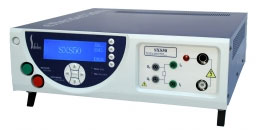
Sefelec manufactures current injection sources in combination with hipot testers in order to answer to some international standard for the high current tests on cable accessories, underground connection accessories, low voltage underground network connection, high voltage cable accessories (outdoor terminations, switchgear terminations, transformer terminations,…)

The concerned accessories are for instance connected to the following standards: NF (C 33-002), NF (C 33-210), … The following European document of harmonization also gives details of the method to follow: CENELEC HD605S1.

Definition:
The long run tests (also called ageing test) are made during several hours, days or months.
The accessories under test are often put under ground, under water, or in the air for the test, and are submitted to thermic cycles by applying an AC current.
An AC voltage is also permanently applied at the same time between phase and ground ; this test is called the hipot test (also called hi-pot test, dielectric withstand test, dielectric strength test, breakdown test, or flash test).
No breakdown (also called flash, arc) should occure during this test.

Example of typical Test:
This ageing test (also called run test) made on the accessories combines a test in current (thanks to a window transformer, also called current injection transformer) at for instance the following AC voltage/current : 20/24/36 VAC, 3 x 700A or 10VAC, 1 x 1200A, …), and a test of hipot (at for instance 2kVAC, 50 mA, 60 kVAC, 200kVAC, …).
A loop is made with the cable.
This loop holds 2 or 4 accessories.

Test specifications:
An example of the duration of the ageing test could be the following one :
210 cycles of 24 hours (8 hours heat up / 16h cooling cooling down) at (100 ± 5) °C
= 5000 hours under voltage
= 7 months

Oscilloscope supports MIPI and SATA Standards

October 2, 2009 by admin  
Filed under Data Acquisition, Featured, New Articles

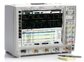
Agilent Technologies Inc. expands its mixed-signal and digital-storage oscilloscope portfolio with two lower-cost 600-MHz Infiniium 9000 Series models, three new application packages and GPIB compatibility. The 9000 Series is the industry’s first oscilloscope family to offer bandwidths from 600 MHz to 4 GHz, and it includes the industry’s first mixed signal oscilloscope to support MIPI and SATA industry standards.

Oscilloscopes are the primary tools engineers use to test and debug electronic designs, and engineers need increasingly broad measurement capability to deliver robust products in a timely manner. Agilent’s lower-cost Infiniium 9000 Series 600-MHz models incorporate advanced viewing and analysis for debugging and testing a wide variety of traditional signals and buses used in embedded designs. In addition, they offer optional logic and protocol analyzer capabilities.

Agilent-9000In addition to extending its lineup with lower-cost models, Agilent has added new applications that capitalize on higher-bandwidth 9000 Series models. Emerging serial bus standards in the wireless mobile industry have created the need for teams to debug and test devices that meet MIPI-DPHY physical-layer standards. Agilent’s 9000 Series is the first mixed-signal oscilloscope to offer MIPI-DPHY compliance test and protocol analysis enabling faster development of wireless mobile products employing MIPI standards. Teams can quickly move from physical-layer to protocol-layer measurements and can use the compliance application to automate testing to ensure compliance with MIPI-DPHY standards.

Development teams working on electronic products that include storage may have cost constraints or legacy requirements that make SATA 1 a better choice than other interface technologies. Engineers using Agilent’s 9000 Series scopes can quickly see SATA 1 information at the physical and protocol layers. For development teams using the faster 3-Gbs SATA II standard, Agilent offers both compliance and protocol support with its Infiniium 90000 Series.

While LAN and USB IO have reduced the need for traditional programming over GPIB interfaces, many engineers continue to rely on programmatic interaction with oscilloscopes via GPIB. Agilent’s new GPIB-to-LAN adapter enables GPIB applications on a computer to interface transparently to an instrument with a LAN interface as if it were a GPIB instrument. This adapter broadens the number of test environments that are ideal for the Infiniium 9000 Series scopes.Agilent-Oscilloscope

“We’ve received great customer reviews on our Infiniium 9000 Series introduced earlier in the year,” said Scott Sampl, vice president and general manager of Agilent’s oscilloscopes business. “Now we’ve extended the family so more customers can use the scope with the industry’s broadest measurement capability.”

Multimeter Works Two Places at Once

October 2, 2009 by admin  
Filed under Bench Test, New Articles

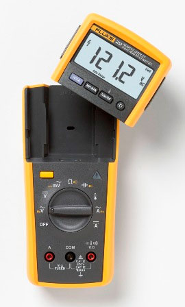
For the first time, a multimeter will allow electricians and electronic technicians to work in two places at once, says Fluke Corp., provider of portable electronic test and measurement technology. Fluke introduced what it calls the industry’s first digital multimeter with a detachable wireless display.

Designed by Fluke engineers and manufactured at the Fluke Worldwide headquarters in Everett, WA, the Fluke 233 Digital Multimeter uses a 2.4 GHz ISM Band wireless transmitter to send measurements to the detached display, improving safety and increasing productivity for today’s busy industrial and commercial electricians and electronic technicians.

Fluke-233In addition to functioning as a highly capable multimeter, the new Fluke 233 Remote Display Multimeter gives users flexibility in unusual test situations. By sliding the wireless display out of the meter body, the user can place the display where it is most easily seen-up to 10 meters (33 feet) from the point of measurement- while putting the meter in the best position to take measurements. There’s no more juggling of leads and the meter while stretching into tight spots. Fluke provides a video demonstration.

Designed for both convenience and safety, the Fluke 233 makes it easier to take measurements in hard-to-reach places, or make measurements in machines or panels that are physically separated from a limit or isolator switch. It is ideal in areas where the operator can’t be close to the active measurement point, Fluke says, like clean rooms or hazardous areas. Making measurements without holding the meter can help users improve their visual focus on their test probes and work more safely.

Fluke says the detachable wireless display lets the user:

- Find a comfortable position to view and record test data, even when the test location is hard to reach or in a dirty or noisy environment.

- View readings when the test point is across the room-or in the next room.

- See test results even when the meter is hidden behind an equipment enclosure.

- Run tests and read results at a safe distance from shock and arc flash hazards, moving machinery and other dangers.

- Separate the tasks of positioning the meter and reading test results, allowing full attention on each job for increased safety.

The low-power, 2.4 GHz-ISM Band wireless signal that transmits measurement data is resistant to electromagnetic interference. The radio transmitter automatically turns on when the display is removed from the meter and off when the display is reattached. The removable display is magnetic and has a flat bottom, so it can be conveniently mounted or placed on a flat surface where it can easily be seen. When the display is attached, the Fluke 233 operates as a conventional multimeter.

The Fluke 233 will measure up to 1000 V ac and dc and up to 10 A. It features a 10,000 μF capacitance range, measures frequencies to 50 kHz and captures min/max and average readings automatically. It features a 6,000-count display and includes a built-in thermometer that enables users to take temperature readings easily without carrying a separate instrument. The meter body is powered by three AA batteries; the display has two AA batteries. Average battery life is 400 hours. An auto-off feature maximizes battery life.

The Fluke 233 is safety rated for use in CAT IV 600V/CAT III 1000 V working environments.