By definition, power factor is a dimensionless quantity ranging from -1 to 1. It is the ratio between real power dissipated in the load and apparent power, which oscillates in the circuit but does not dissipate in the load and consequently does not perform useful work.
The value of the power factor depends upon the nature of the load. In a purely resistive load such as an incandescent light bulb or electric heater, the power factor is close to 1. (There is always some inductance in any conductive body.)
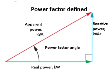 Reactive loads, either inductive or capacitive, lower the power factor, necessitating use of larger conductors and devices though the reactive component performs no useful work. Also, there is wasted power. This is costly and undesirable for the utility. When the power factor is less than one, the cost usually gets passed on to the customer in the form of a power factor penalty added to the utility bill.
Most premises loads, especially in industrial or large commercial facilities, have a significant inductive component. Motors, transformers, and other magnetics — as well as fluorescent light ballasts and nonlinear electrical equipment — contribute to this imbalance. Capacitive loading is less common. When there is capacitive reactance, it is algebraically subtracted from the inductive load to find the net reactance. This is in contrast to the way resistive and reactive loads are added, which is vectorial, because they are out-of-phase.
Capacitive loads can be shunted across the line to intentionally correct unwanted inductive power factor. Similarly, more expensive synchronous motors can be used to counteract the power factor contribution of induction motors. Power factor correction in the form of large capacitors in metal enclosures gets deployed at the generating station, at any point along the distribution line, or at the customer facility.
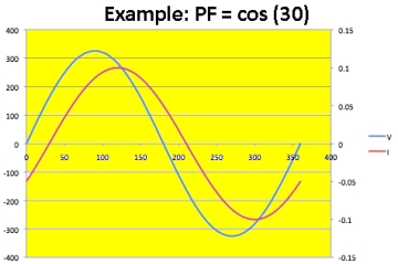 Power factor, caused by a net inductive (or possibly capacitive) loading, arises from the fact that the applied voltage and measured current waveforms are out of phase. Their peaks occur at different points in time, as shown along the Y-axis of and oscilloscope when it is operating in the time domain. It is easy to see why this happens. The amount of current in a reactive load relates not to the amplitude of the applied voltage, but to the rate of change of that amplitude. Examine the graph of a sine wave and you will see that the slope is near vertical as it crosses the Y-axis and near horizontal at its peaks. When the amplitude of the applied voltage is high, the rate of change is low, and when the amplitude is low, the rate of change is high.
In an inductive load, the current waveform lags the voltage waveform. Energy needed to build the magnetic field where it is stored requires a definite amount of time to do so, and another time interval elapses as the energy is returned to the electrical circuit. If the load is capacitive, the
current waveform is said to lead the voltage waveform, where electrical energy is stored in the dielectric medium in the form of an electrostatic charge. (Current does not actually flow through a capacitor, but the effect in an electrical circuit is equivalent.)
The amount of temporal separation between the voltage waveform and the current waveform — in other words the degree to which they are out of phase — is expressed as power factor. The oscilloscope is the preferred instrument for visualizing and measuring power factor in a real-world electrical system and also to ascertain the contribution of an individual motor or other device.
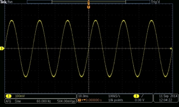
First, we’ll discuss the situation where the waveform is sinusoidal. An oscilloscope with conventional probing is a simple voltmeter but one that displays a graphic representation of the voltage plotted with respect to time. In addition and simultaneously, an oscilloscope having at least two analog input channels is capable of displaying the current waveform of that signal, plotted against the same amplitude (Y) and time (X) axes. The two aspects of the signal may be shown superimposed or in split-screen format.
Voltmeter leads are attached so the instrument is in parallel with the power source or load. An ammeter current reading, in contrast, uses leads connected in series with the power source or load. Using a conventional ammeter (usually a milliammeter) requires cutting into one of the circuit wires or device leads and later re-soldering or re-terminating it. Moreover, because all the current, in accordance with Kirchhoff’s Current Law, passes through the meter, this method is not feasible for large loads.
In making a voltage reading, the meter hookup is not problematic as long as CAT voltage restrictions are observedsince — the memter has a high impedance and is shunted across the circuit. In either low-impedance ammeter or high-impedance voltmeter readings, the circuit should not be loaded significantly.
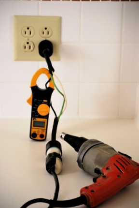
To avoid the problems mentioned above when taking current readings, there is an alternative to the ordinary ammeter. It is the clamp-on ammeter (trade name Amprobe). This meter, long favored by electricians, has jaws which open so a conductor can be inserted. Thus there is no wire cutting or stripping involved. And the conductor needn’t be perfectly centered in the probe; it can pass through at an angle. Also it doesn’t have to be motionless, so vibration present in leads to a running motor won’t compromise accuracy.
The jaws contain a coil to detect the magnetic field surrounding a body conducting electricity. There is no direct electrical connection between the meter and the power source, so there is no danger of overvoltage unless it is so extreme that arcing takes place. Beyond a certain level, the core becomes saturated and no further transfer of energy takes place.
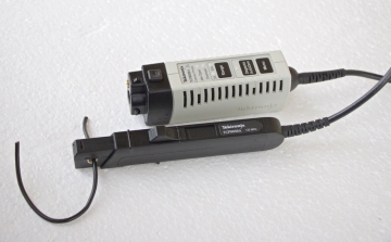
As an oscilloscope accessory, a current probe is available and it is essential for many types of work, including power factor measurements. The oscilloscope current probe resembles the electrician’s clamp-on ammeter, except it is somewhat smaller. Some models have jaws that are not insulated, so bare wire without a sleeve should not be inserted.
To measure motor power factor using an oscilloscope, first ascertain that voltage limits of the oscilloscope will not be exceeded. Then, configure one channel to measure voltage, using a conventional 10:1 attenuation probe, and configure another channel to measure current, using the current probe. Display both signals simultaneously.
Using cursors, measure the phase angle between the two waveforms. This important equation relates power factor and phase angle —
The power factor PF is equal to the cosine of the phase angle:
PF = cos(φ)
Where PF is power factor, Φ is phase angle.
It may be that the motor lead is too large to go into the oscilloscope current probe jaws, and/or the current rating is too high for the current probe. In this instance, consider building your own using an appropriately-sized current transformer. This is a copper coil that is used by utilities to meter current in large conductors. Because the wire is not adequately insulated for the voltage, it is suggested that the hookup be completed while the circuit is powered down.
So far we have been discussing the measurement of power factor of loads where the current is sinusoidal. But many electronic loads alter the utility-supplied power so a non-sinusoidal waveform appears in the current measurement. This is the case when the circuit consists of a bridge rectifier that incorporates a capacitor filter. The current waveform will consist of two relatively large, brief pulses per cycle. This situation is disadvantageous for the utility because their equipment must include conductors, transformers and switch gear that are capable of handling the peak currents, which will not be reflected in watt-hour metering due to the short duration.
The oscilloscope is able to see this type of distortion and in Fast Fourier Transform (FFT) mode, the distortion can be quantified in terms of harmonics that exist alongside the fundamental, but do not provide usable power.
Care must be taken when using an oscilloscope to measure line voltages and current. Any connection of the ground return lead to a hot line that is referenced to but floats above ground potential can be disastrous for the instrument.
An isolation transformer is one solution. Grounding does not pass through a transformer unless – and this is a distinct possibility – there is an electrical connection, internal or external, between the primary and secondary.
Measuring power factor of necessity involves working with high utility voltage (even higher in a VFD dc bus) and high levels of available fault current, so the user must become aware of potential hazards before undertaking any measurements.

Great article. Also study article about the measurement of power factor using micro-controllers here.
http://engineerexperiences.com/power-factor-measurement.html