 Pickering Interfaces launched a new family of 110 high-accuracy programmable resistor modules with 2.5W, 5W or 10W power handling capability at 100V or as limited by power. Models 40-251/2/3 target applications that require accurate medium-power programmable resistance such as a programmable load for the testing of Electronic Control Units (ECUs) and fuel level sensing. These ECUs are commonly used in the demanding, hi-reliability, Automotive, Military and Aerospace sectors.
Comments Paul Bovingdon, Simulation Product Manager at Pickering Interfaces: “By offering such a huge choice of resistance channel counts, ranges and setting resolutions, we are addressing a wide variety of medium-power electronic Test & Measurement applications, delivering test engineers exactly what they need rather than forcing them to accept a compromise.
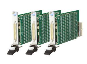
Available in modular PXI format for flexible and scalable system integration, the model 40-251/2/3 resistor modules are compatible with a wide range of chassis, including PXI, PXIe Hybrid, cPCI and Pickering USB/LXI chassis, for flexible functional test system integration. With between 1 and 8 resistance channels per module, resistance settings from 1Ω to 22MΩ and resolutions from 0.125Ω to 2Ω, the most suitable module may be selected for any specific application.
Resistor channels are simply programmed by the use of resistance calls to the software driver. Each channel can be set as short or open circuit to simulate a wiring or sensor fault, and simplified DMM module verification is provided via an optional calibration cable.

Leave a Reply
You must be logged in to post a comment.