Performance qualities once only available in exotic instruments can now be found in gear designed for production testing.
5G has now made the jump from research to mainstream adoption, and most chip manufacturers are well down the road to developing second or third-generation components. In the early R&D phase, it was important to push one or two devices through millions of test scenarios. Early testing focuses on conducting every conceivable measurement to understanding what’s possible with the new 5G device. But that changes by the time a part goes into production, when the testing regimen focuses on having a well-established set of parameters for what constitutes a validated part.
Today, most 5G device manufacturers are testing more products but running fewer tests on each one. R&D teams still need custom, lab-oriented equipment. But many RF engineering teams are at a point in the design cycle where they don’t need a full complement of test functions. Instead they need test equipment, specifically signal generators and signal analyzers, that can handle production-level characterization and validation at a lower price point.
In the R&D phase, 5G test and measurement equipment fulfilled a wide range of demanding requirements for component characterization in all specified frequency ranges. Tasks included supporting both sub-6 GHz and mmWave signals, while providing dedicated 5G NR measurement options. These options fully supported the 5G NR flexible numerology, e.g. in terms of subcarrier spacing and multiple bandwidth parts.
Features included outstanding RF performance like high frequency and high bandwidth signal generation and analysis with extreme performing power flatness, phase noise reduction and EVM (error vector magnitude, sometimes also called relative constellation error, RCE) performance. Other aspects are full range of massive MIMO testing, ranging from true multiport real-time analysis of conducted cross-coupling effects at antenna arrays, going up to near-field and far-field over-the-air measurements.
R&D test & measurement systems that offer all of these capabilities are more sophisticated (and therefore more expensive) than equipment for 5G device production.
Production-level 5G testing
As design margins shrink over the course of a design lifecycle, cost reduction can’t come at the expense of performance. In particular, accurate EVM is important because it represents some of the device’s most critical performance qualities. As a result, EVM performance has become a valuable benchmark for device evaluation. The benefits of getting EVM right cascades throughout the entire system.
Consequently, it may be useful to review a few EVM basics and how they relate to 5G system performance. An error vector, of course, is a vector in the I-Q plane between the ideal constellation point and the point the receiver decodes. Said another way, it is the difference between actual received and ideal symbols. Imperfections such as carrier leakage, low image rejection ratio, phase noise, and so forth deviate the actual constellation points from the ideal locations. The EVM is the root mean square (RMS) average amplitude of the error vector, normalized to ideal signal amplitude reference.
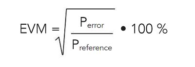
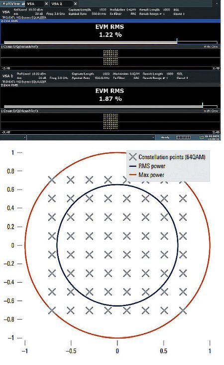
EVM is generally expressed either in percent or in decibels, dB. The ideal signal amplitude reference can either be the maximum ideal signal amplitude of the constellation or the RMS average amplitude of all possible ideal signal amplitude values in the constellation. Unlike MER (modulation error ratio) for example, which per definition is normalized to the mean power of the reference signal, EVM normalization is not predefined.
While there is generally no confusion about the error power, there are two widely used versions of the reference power that can make a significant difference in the EVM reading.
In many cases, the EVM references the mean (RMS) power of the reference (ideal) signal. Some applications also use the peak power of the reference signal as the reference power. Obviously, there is no right or wrong here. It is more a question of the measurement task and the expected results.
Most generic Rohde&Schwarz measurement personalities give users a choice of reference powers. The (often unchanged) default setting is the RMS power. But a point to note is that in looking at only the symbol instants of a QPSK signal (where EVM is typically evaluated), there is no difference between RMS and peak power, because all symbols have the same amplitude.
For a 64QAM signal, use of RMS or peak power can make a significant difference – up to 3.7 dB. APSK or higher-order QAM modulations may result in even greater differences. The decision to use peak or RMS normalization depends on the application – but comparisons should only compare apples to apples.
Measurement challenges
The higher frequency ranges of up to 54 GHz for 5G represent a steep jump in complexity for testing and measurement. One of the inherent challenges with 5G is the high-bandwidth signals that hit every element of the RF front end – antenna, amplifier, transceiver, etc. Measurement of integrated power over a particular bandwidth requires optimizing the signal-to-noise ratio by not over-ranging the instrument. When both the signal and noise are broadband, it takes instrumentation with a high EVM performance over a wide bandwidth to make accurate measurements.
For example, the third-order intercept specification on a spectrum analyzer dictates the high end, which might not typically be a consideration for EVM. Because 5G signals are wideband with high peak-to-average ratios, it’s easy to exceed the power limit of the analyzer front end and get an error.
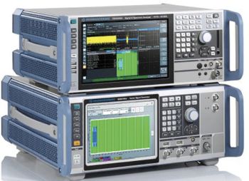
Insight into the dynamic range limits of RF components comes out of the ability to see the lowest level signals in the presence of higher power, high data rate, and wide bandwidth signals. SEM performance is important because it identifies spurious signals, or spurs, that can originate either from both the device under test (DUT) and from the test instrumentation itself. A spur that coincides with the frequency of the measured signal can produce inaccurate ACLR or EVM measurements.
Spurious signals become more frequent as you move downmarket from high-end test equipment to instruments built for broad adoption. But there are options available that deliver good spur performance at a mid-range price. Phase noise is another important specification to consider in an RF test platform because it’s one of the main factors that can determine EVM performance. Good phase noise doesn’t guarantee good EVM, but poor phase noise will always result in poor EVM that cannot compensate for it in other areas.
To field mid-range instruments that perform well, test equipment providers are starting with high-end equipment that already provides excellent measurement quality and working backwards. This approach allows making decisions about which performance areas to scale back for reasons of cost. The resulting instruments still provide upper-range performance for the measurements that matter. Starting from a high-end design does much more to preserve the quality of the measurement capabilities than starting from scratch and striving for some theoretical benchmark.
The latest signal generators and signal analyzers, thanks to this approach, represent a significant improvement over what has been possible even with high-end platforms. It’s not uncommon to see instruments handling frequency ranges of up to 44 GHz and analysis bandwidth of 1 GHz, both necessary for the complexity of emerging 5G standards (3GPP Release 15 and beyond). In fact, some of these specifications and techniques to optimize data rates require up to 1 GHz bandwidth. This requirement in itself represents a significant inflection point that will pressure test groups to upgrade their test systems to handle the latest standards.
A fast, integrated, out-of-the-box solution can help test teams cover a lot of ground and reduce the time to first measurement. Multithreaded processing and server-based testing–where results can be processed centrally while the instrument is used only to capture IQ data–can help minimize test times.
In addition, automation features such as context-sensitive help and a built-in SCPI (standard commands for programmable instruments) macro recorder with a code generator helps speed production testing. As with many RF measurements, 5G production test instruments must also correct for the test set-up impedances. In this regard, it is helpful to use instruments providing an S2P file (s-parameter file) for all of the measurement components between the instrumentation and the DUT. This shift of the measurement plane closer to the DUT produces a more accurate measurement.
As 5G R&D shifts to 5G device manufacturing, test costs and speed become driving factors. However, performance still matters, so it’s wise to place a premium on instruments that can meet the demanding analysis bandwidth and frequency range coverage of 5G.




Leave a Reply
You must be logged in to post a comment.