If a stairway, hallway or room has two separate entries, three-way switches make sure occupants will not have to cross a room in darkness to switch on the lights. Three-way switches are also useful for controlling outdoor lighting between two buildings and to control lights in a detached garage from within the main building.
Most home owners and tradesworkers can wire conventional single-pole switches without a problem, but when it comes to three-way switches, many become baffled and end up calling in a professional electrician to sort things out. Here are a few principles that will make for a correct and efficient installation that will work the first time:
Two three-way switches necessarily sit some distance apart, but electrically they constitute a single “black box.” Together they function as one conventional single-pole switch whose sole function is to turn on and off the load.
It is easier to wire this black box/switch configuration as an in-line configuration as opposed to a switch loop, which requires more wire and is more complex because of the new Code mandate to provide a neutral in every switch box.
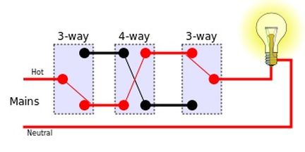
One three-way switch is the input for the pair and one is the output. Three-way switches have one terminal at one end of the switch body. On the input switch, this is for the single black (hot) conductor from the power source such as an entrance panel. At the output switch, a single black conductor goes directly to the load. The white wires are not connected to either switch. They pass through the enclosures and connect to the load, as does the green or bare equipment-grounding conductor.
At the other end of each three-way switch body are two terminals. These are for the two alternate current paths inside the black box, between the two three-way switches. At any given time, one of these wires is energized and the other is not. A specialized three-conductor cable runs between the two switches. To one terminal of each, the black conductor is connected. To the other the red connects. It doesn’t matter which is which. The red and black conductors are called in the trade “travelers.” To inject a bit of humor into an otherwise dry topic, I call them “politicians.”
The third conductor is white, and it is not connected to either switch. It is connected (using wire nuts) to white conductors in each enclosure so there is continuous neutral continuity between the power source and the load. The same is true of the bare or green equipment-grounding conductor. Be sure to connect it to the ground straps of the switches and to all enclosures if they are metal.
Four-way switches are used for applications that need more than two switching locations. They are easier to understand than three-way switches. They have two terminals at each end of the switch body and connect to the travelers in-line between the three-way switches, in-coming at one end of the switch body, out-going at the other end. It doesn’t matter which way the four-way switches face. Red and black connections may change any number of times between the input three-way switch and the output three-way switch.
That’s all there is to it. Follow these basic principles and your three- and four-way installations will always work. If in doubt, use an ohmmeter to ring out the terminals of these devices.
Three- and four-way dimmer switches are also available. They are wired in the same way and can add ambiance to a living room or dining room. (Note, though, that CFL bulbs generally won’t work on dimmers. Some LED bulbs will work, but some won’t. Dimmer compatibility is called out on the bulb packaging.)

Four way switch