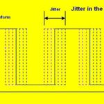
Jitter–basically the deviation between true and measured periodicity–is harmful beyond a certain level. In measuring jitter, we are calculating RMS, peak-to-peak deviation or spectral density. Jitter at frequencies below 10 Hz is known as wander.
High-frequency signals are more prone to jitter than low-frequency signals. The deviation in periodicity that constitutes jitter may be in amplitude, phase timing or pulse width. Symptoms include flickering of a display in a computer monitor, server and processor anomalies, audio and video artifacts and cross-network latency variation. Underlying causes may be timing drift, network congestion or route alterations. Additional problems include insufficient bandwidth, less than optimal hardware, wireless as opposed to Ethernet connectivity and neglecting to implement packet priority. For Voice over IP, audio should have priority over other traffic.
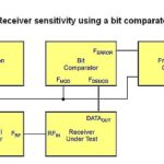
The typical approach to find out whether the measured level of jitter in a system is acceptable is to compare its permissible Bit Error Rate (BER) with a standard, such as 10-12 for Ethernet. This metric is comprised of total jitter, which is the sum of random jitter and deterministic jitter. Random jitter, otherwise known as Gaussian jitter, consists of unpredictable timing noise. Therefore, it conforms to a normal distribution because its cause is thermal activity in an electrical circuit. In contrast, deterministic jitter is predictable. Its peak-to-peak value is bounded. The bounds are knowable and can be observed. Their known non-normal distribution is data-dependent, correlated to the data stream.

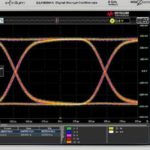
In detecting and measuring jitter, engineers typically use eye patterns. The eye pattern is an oscilloscope display in which a signal at the receiver is applied to the scope vertical input. Data triggers the horizontal sweep. In its most generic form and with appropriate persistence applied, the eye pattern resembles one or more human eyes situated between a pair of horizontal rails.
An eye pattern corresponding to an undistorted transmission is usually characterized by the fact that the superimposed traces stay put, forming the outline of nice, alert, open eyes. If the transmission undergoes distortion, notably due to timing jitter, the traces will take random, significant shortcuts across the no longer open eyes.
Unfortunately, only a well-equipped, high-bandwidth oscilloscope will suffice to study eye diagrams, and it must have jitter analysis software. Moreover, the user must be adept at setting it up and interpreting the results.

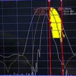
One interesting jitter analysis tool found on scopes is a histogram display of the jitter waveform. Histograms provide a visual display of the statistical distribution of the measured parameters such as the width jitter of a waveform, ie, the distribution of edge crossings. The height of the histogram is correlated to the odds that the actual waveform edge will be that distance from the ideal edge. In addition to the histogram display, jitter analysis packages will typically display the sigma (standard deviation) and range of the distribution.
 The shape of the histogram can provide important information about the jitter in the waveform. A bimodal shape is indicative of deterministic jitter caused by system or data-dependent issues. On the other hand, a histogram with a Gaussian distribution means the jitter arises from random noise.
Another useful analysis tool is the jitter trend. The jitter trend waveform is a plot of the timing errors of each of the data edges relative to the recovered clock (vertical axis) versus time. This waveform is

time-correlated to the captured serial data signal. The trend plot can reveal sources of deterministic jitter such as some kind of modulation, as well as extreme timing errors. Running a spectrum analysis on the jitter trend waveform can provide further insights such as the frequency range of the jitter components.
A point to note is that the scope itself has some jitter. The jitter contribution inherent in the oscilloscope measurement arises from several sources that include trigger jitter, timebase stability, and delay jitter. Jitter due to the scope is typically in the range of tens of picoseconds. Scope jitter can be minimized by various means including the use of zero delay, using a trigger signal with a high signal-to-noise ratio, and maximizing the measured waveform dynamic range by operating close to the full scale range of the selected Volt/Div setting.
Moreover, scope jitter sources are generally uncorrelated with those of the DUT so they can generally be subtracted from the measured data using quadrature subtraction:
tDUT = (tmeas2 – tscope2 )1/2
Where tDUT = jitter of device under test, tmeas =total measured jitter, and
tscope= jitter caused by the scope. The jitter due to the scope should be measured under the specific conditions of the test taking place.

Leave a Reply
You must be logged in to post a comment.