The IQ Fiber Master MT2780A multi-port CPRI-based RF and PIM (passive intermodulation) analyzer that is the first instrument to perform true PIM analysis over fiber and present RF spectrum results derived from IQ data. The MT2780A reduces test costs and time by providing field engineers, field technicians, and third-party contractors with a single instrument to conduct RF interference measurements and PIM troubleshooting on LTE-based systems using CPRI front haul infrastructure.
The IQ Fiber Master leverages patented PIM-over-CPRI and RF-over-CPRI measurement 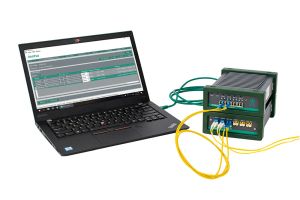 capabilities that allow tests to be conducted on the ground, significantly reducing tower climbs. Field engineers and technicians can use the MT2780A to scan the uplink RF signals of a remote radio head (RRH) for in-band interference while simultaneously conducting PIM over CPRI measurements. Supporting all Tier 1 LTE base station radio manufacturers, the single instrument solution can determine if KPIs are being affected by interference or PIM.
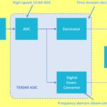
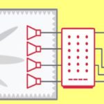
Analyzing CPRI IQ data allows users to view a radio’s uplink spectrum for interference troubleshooting. The IQ Fiber Master measures PIM over CPRI with four SFP inputs, providing the ability to compare multiple bands and sectors, as well. Measurements are performed on live cell tower traffic signals, providing a unique method to conduct real-world testing that results in improved accuracy and no system downtime for test. As measurements are derived from baseband IQ data, the IQ Fiber Master can make measurements on any frequency RRH, or combination of frequencies of the RRH, providing a very cost-effective solution.
The IQ Fiber Master analysis results provide a full PIM diagnosis. It will report the presence of PIM, whether it is internal or external, and the distance to PIM. In addition, the unique and proprietary PIM heatmap quickly displays which transmitter contributes the most PIM. This collective diagnosis data shortens the entire PIM hunting exercise by directing field engineers and technicians to the most probable location and cause of the issues.
For on-going monitoring, IQ Fiber Master can be installed at cell sites to conduct long-term PIM over CPRI measurements and provide analytical information. PIM-related problems, such as intermittent PIM occurring on specific days and times or changes in PIM due to base station load during the day, can be measured in this configuration. Reports of the measurements can be generated and used for comparative analysis.
The IQ Fiber Master MT2780A also serves as a band-less PIM testing solution that can be a carrier’s first test tool when identifying an interference problem and its location. This helps to determine the most efficient course of action to follow.
All LTE bands are supported by IQ Fiber Master MT2780A. Extremely compact and lightweight, it weighs only 1 kg (2.2 lb) and measures 185x133x55 mm (2.1×7.3×5.2 in), so it fits in the palm of the user’s hand.
Anritsu Co., www.anritsu.com


Leave a Reply
You must be logged in to post a comment.