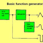
Early signal generators, dependent upon vacuum-tube technology and subject to failure, were ancestors of today’s far more precise and durable arbitrary function generators. These instruments have advanced modes and functions that figure prominently in research and product development as well as troubleshooting and repair.
Here the word “arbitrary” means the instrument is capable of generating custom signals designed by the user. We’ll examine some methods using the Tektronix AFG31000 Series arbitrary function generator.
When powered up, the Tek AFG requires a few seconds to boot, whereupon it goes to the Home Page. This page displays on-screen icons labeled Basic and Advanced, either of which can be accessed by mean of the touchscreen or front-panel buttons.
Basic brings up a window that permits the user to activate any of the 12 internal waveforms: Sine, Square, Ramp, Pulse, Noise, Sin(x)/x, DC, Gaussian, Lorentz, Exponential Rise, Exponential Decay and Haversine. Additionally, if an arbitrary waveform has been created, it can be activated.
The instrument has two channels, so the same or a different waveform can be activated simultaneously. On-screen tabs permit the user to set frequency, phase, amplitude and offset of the waveform(s). Another on-screen menu permits the user to invoke continuous (the default), modulation, sweep or burst modes.
The chosen waveforms are displayed in split-screen format at the bottom. Output ports at the bottom center of the front panel permit the user to send the chosen waveforms via BNC cables to another instrument such as an oscilloscope, or to use breakout cables to inject the signals into circuitry under investigation. To use the outputs, the channels have to be powered up individually by pressing the adjacent On buttons.
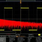
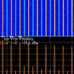
With the two signals from the arbitrary function generator displayed in the oscilloscope, they can be subjected to a vast amount of processing. For example, pressing Math>Dual Waveform Math, the two signals can be added, subtracted, multiplied or divided. Pressing Edit Math Expression, trigonometric functions can be applied, square and square roots extracted, and they can be differentiated and integrated and logarithm accessed. Going back to Math, the user can press the soft key adjacent to FFT and turn Multipurpose Knob a to perform a Fourier transform and display either of the signals in the frequency domain.
Pressing the Home button, we can now use the touch screen to go into Advanced Mode. Basic Mode has an Arb Builder, permitting the user to create and display simple arbitrary waveforms. Sometimes, however, the intended application is more complex and challenging, and creation can only be performed in the Advanced Mode. For example, long waveforms and waveforms with complex timing are best generated in AFGF31000 Advanced Mode. Applications in this category also include synthesizing pulse trains and data packets in serial buses.
Sequence in Advanced Mode is used to control the way in which waveforms are arranged. Typical submodes are repeat, wait, jump, go to and triggering with events such as external and manual trigger, times and SCPI commands.
 Each point in an arbitrary waveform is conveyed in the course of every cycle, timed by the sampling rate without skips or repetitions. Where an application is impacted by jitter and phase noise, as in serial bus simulation and I/Q modulation, and in order to simulate brief anomalies in long waveforms, Advanced Mode has solutions. Waveform detail is retained, jitter and phase noise mitigated and sampling is stabilized over successive cycles.
Advanced Mode has four available outputs: Sequence, Continuous, Triggered and Gated. The user can access a saved waveform by choosing sequence. For waveforms with complex timing, flexibility is enhanced. Waveforms up to 16 MB per channel (or optionally 128 MB per channel) can be organized in as many as 256 steps, consisting of loop or go to, or triggered by jump or wait events.
In Continuous Mode, the AFG31000 arbitrary waveform generator when running maintains a one-step waveform sequence. In Triggered Mode, a single waveform cycle initiates in response to a trigger signal. Then it returns to its initial state until receiving another signal. Gated Mode resembles Triggered Mode except that the action is initiated by a gate signal.
The Sequence Table is an index that lists Advanced Mode outputs complete with loop and conditional jump. The user selects the sequence and the instrument defines the output waveform. The user can also specify the order of multiple waveforms. Referring to the advanced output mode, the user can choose among available waveforms, select sequence to open a saved waveform and create and save a new waveform.
Referring to the advanced sequence list screen, the user can open an existing waveform sequence, initiate a new single sequence, save a waveform or Save As to save a waveform with a new file name. In initiating a new sequence, a dialog box permits the user to save a previous setting if it has not been closed.
 The Advanced Waveform List opens an existing waveform, locates the waveform in the AFG31000 memory, locates the waveform on an external USB drive, locates the waveform in a predetermined memory location or deletes one or more waveforms from the waveform list.
The Advanced Setting Bar permits the user to monitor the status of Advanced Mode in the AFG31000. Sequence displays a range of waveforms based on definitions in the sequence table. In Continuous, the instrument outputs a single waveform repeatedly when running in Triggered. One cycle of a waveform is output when the AFG receives a trigger input. After a single cycle, the instrument returns to its initial state and awaits another trigger input. In Gated, the AFG outputs a single waveform sequence when the gate signal is received and stops when a second gate signal is received.
 In the channel 1/2 Setting Bar, Scale is the scaling amplitude based on offset in a sequence of waveforms in one channel. Offset is the average of maximum and minimum voltage in a sequence of waveforms on a single channel after waveforms are dragged into the sequence table. Scale and Offset work together. Scale value is calculated based on the offset settings.
 The Setting Bar enables users to determine the sampling rate and to set the timing for the signal generating function. An advanced table associated with the setting bar includes these functions:
• Repeat continues the signal generation function until the user issues a stop instruction.
• Wait event must occur to initiate waveform generation.
• Jump event triggers the AFG31000 to proceed to a new step.
• Jump Addr determines the destination for a jump event.
• Go To shifts to a specified sequence location after a waveform is generated in one of the sequence elements.
 Sequence Mode can initiate any of several elements including: Wait/Jump event selection with Off or timer, external trigger, SCPI command or manual; a waveform output begins if Wait is on, when the waveform output starts; Repeat, which defines the number of times the entry is repeated, ranging from one to infinity; only when Jump is on, when a Jump event occurs, the waveform output stops and the sequencer moves to the Jump address; Go To causes the Sequencer to move to the Go To address.
Sequence Mode consists of –
• Event selection: Off/Timer, external trigger, SCPI command and manual.
• If Wait is on, the waveform output begins following a Wait event;
• Repeat sets the number of times the entry waveform repeats.
• Jump, when on, interrupts waveform output following a Jump event. The Sequencer moves to the Jump address.
• Go To: The Sequencer moves to the Go To address when the current waveform is complete.


Leave a Reply
You must be logged in to post a comment.