A variety of measuring instruments may be used to detect and diagnose malfunctions in electric motors. In particular, the insulation resistance tester (or megohmmeter), generally known by its trade name Megger, can provide critical information regarding the condition of motor insulation. In an industrial facility, the recommended procedure is to perform periodic tests and record the results so damaging trends can be detected and corrected to prevent an outage and extensive downtime.
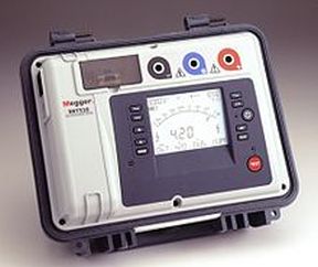 The insulation resistance tester resembles a conventional ohmmeter. But rather than the typical three-volt test voltage derived from an internal battery and present at the probes, the Megger provides a much higher voltage. It is applied for a proscribed length of time. The leakage current through insulation, expressed as resistance, is displayed so it can be graphed. This test may take place on installed or on-the-reel cable, tools, appliances, transformers, power distribution subsystems, capacitors, motors and any type of electrical equipment or wiring.
The test may be non-destructive, for in-service equipment, or prolonged at elevated voltage to test prototypes to the point of destruction. In using the Megger, a bit of a learning curve is involved. The correct settings, connection procedures, test durations and safety precautions must be implemented to avoid damaging the equipment or electrocuting the operator or coworkers.
The motor under test must be powered down and disconnected from all equipment and wiring that is not to be included in the test. Besides invalidating the test, such extraneous equipment could be damaged by the applied voltage. Additionally, unsuspecting individuals could be exposed to hazardous electrical energy. This is because the applied voltages are of necessity high.
All wiring and equipment has an inherent amount of capacitance, which is generally significant in large motors. Because the equipment is in effect a storage capacitor, it is essential that lingering electrical energy be discharged before and after each test. To do this, shunt the relevant conductor(s) to ground and to each other before reconnecting the power source. The unit should be discharged at least four times as long as the test voltage was applied.
The Megger is capable of applying different voltages, and the level should be coordinated with the type of equipment under test and the scope of the inquiry. The test generally aplies between 100 and 5,000 V or more. A protocol involving voltage level, time duration, intervals between tests and connection methods must be composed, taking into account the type and size of the equipment, its value and role in the production process and other factors.
A very valuable manual with the wonderful title A Stitch in Time is available at no cost at www.biddlemegger.com/biddle/Stitch-new.pdf. Another useful text is IEEE’s Recommended Practice for Testing Insulation Resistance of Rotating Machinery.

Leave a Reply
You must be logged in to post a comment.