Waveforms other than those that are pure sine waves or sinusoidal will have a portion of their energy in frequencies other than the fundamental. These frequencies are known as overtones. Some but not all overtones are harmonics. The difference is in how we define them.
A harmonic has a frequency that is a whole integer multiple of the fundamental. If it is two or three times the fundamental frequency, for example, it is a harmonic. If it is 2.5 times the fundamental, it is not a harmonic, but an overtone.
What is special about a harmonic? If you view the fundamental and the harmonic in a single oscilloscope display, you will notice that at regularly repeating intervals along the time domain (X) axis, the peaks will coincide. That is a natural consequence of the fact that the harmonic is a whole-integer multiple of the fundamental.
Harmonics are what make music interesting. A pure sine wave as produced by a tuning fork has a stark quality that is distinctly unpleasant at high volume. The great variety of musical instruments including the human voice produce sound that is rich in harmonics in different proportions. An electronic keyboard can easily synthesize any fundamental at half-step intervals within its frequency range together with harmonics at required proportions to accurately convey the sounds made by a great variety of musical instruments.
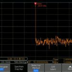
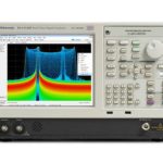
If you extracted this output and fed it into the RF port of an oscilloscope such as the Tektronix MDO3104, you could view the signal in the frequency domain. This would show the harmonics adjacent to the fundamental with relative amounts of power in decibels.
Unlike audio harmonics, harmonics in an electrical system are generally harmful and as far as possible are to be avoided. Many electrical engineers specialize in the field of power quality which can be viewed as the science of reducing or mitigating harmonics and other electrical noise on power lines. Their diagnostic tools of choice are the oscilloscope and the spectrum analyzer.
The electrical output produced by a rotary generator is close to a pure sine wave with a minimal harmonic component. In the early years of ac electrical distribution, harmonics were not a problem to the extent that they are today. The biggest issues centered on the creation of electrical noise caused by arcing brushes in electrical motors and arcing contacts in the great number of relays that were part of the accelerating industrial revolution.
Now an entirely different problem has emerged. It is caused by the vast proliferation of non-linear loads. A simple resistive load, such as incandescent lighting or a heating element, is known as a linear load. This means there is a linear relationship between the voltage applied to the terminals of the load and the current that it draws. Non-linear loads, in contrast, draw current that is not directly proportional to the applied voltage as supplied by the utility.

Examples of non-linear loads include electronic fluorescent ballasts, battery chargers, variable frequency drives and switching power supplies. The current as drawn by these non-linear loads is characterized by non-sinusoidal waveforms, often with steep rise and fall times. The amount of power contained in the harmonics varies with the steepness of the rise and fall times of the current waveform.
In accordance with Kirchhoff’s current law, the same amount of current flows through any part of a series circuit. Therefore, the utility-supplied ac waveform is distorted when these loads are connected. More specifically, the distortion arises because of the source impedance of the nonlinear loads. (Recall that nonlinear loads have input impedances that include reactive components that vary with frequency. Thus the reactive portion of the impedance will have one value for the fundamental power line frequency and different values for each of the harmonics.)
The distortion appears throughout the electrical system and manifests in overheated motors, transformers and conductors. These must be oversized or else the source of the harmonics must be eliminated.

Leave a Reply
You must be logged in to post a comment.