By far the most used oscilloscope probes are the passive 10:1 attenuation probe. It is appropriate when the frequency of the signal under investigation is less than 600 MHz. Impedance matching from the probe tip to channel input port is critical. A mismatch gives rise to reflections, collisions and loss of data. At dc to the mid-megahertz range, impedance consists primarily of resistance, but as frequency rises, capacitive and inductive reactance play an increasingly prominent role in signal attenuation.
The 10:1 passive probe offers less bandwidth and imposes heavier capacitive loading than an active probe. Inductive loading, also heavier in the passive probe, can be partially mitigated by using a shorter ground return lead and keeping it as straight as possible. (Even a partial turn at high frequency is, in effect, a fractional-turn coil.) By the same token, an active probe can tolerate a longer ground return lead where necessary. Passive probes, in general, are satisfactory for debugging and troubleshooting many circuits. But at 600 MHz plus, it may be necessary, depending on the amount of accuracy demanded by the application, to bring out the far more expensive active probe.
Active probes succeed in practically eliminating reactive loading of the circuit under investigation by means of a small solid-state amplifier in the probe body adjacent to the tip. The device has high input impedance because of insulated gate technology. Drawing virtually no current it has little discernable effect on the circuit that is probed.
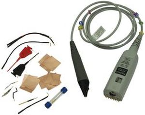
Active probes are more costly. The Keysight 1-GHz N2795A active probe is $1,111. The Keysight 2 GHz N2796A active probe is $2,253. Both have an input impedance of 1 MΩ, 1 pF and a dynamic range of 0 to ±8 V.
From a practical standpoint, a major difference between active and passive probes is that active probes require power, either an internal battery or an external dc power supply.
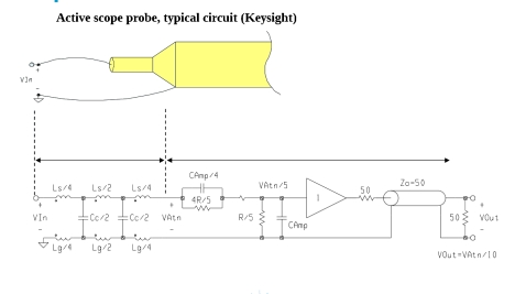
In the active probe body, there are additional components. Besides amplification, there is signal filtering and also the capability for varying amounts of automation between probe and oscilloscope. When you plug the active probe cable connector into the analog channel input port, the oscilloscope detects the active probe type and characteristics. Depending on the manufacturer, it may permit the user to refine measurement and display.
Active probes differ from passive probes in other respects. Their dynamic range is lower, typically three to eight volts. They can be damaged by probing above rated voltage and also by electrostatic discharge. To limit electromagnetic interference, the ground return lead may be screened. In addition to 1 MΩ impedance as seen by the circuit under test, the capacitive reactance is often less than 1 pF.
The user may introduce an offset voltage to augment the limited dynamic range by adjusting the center point. In this way, an active probe with ±2.5-V dynamic range can read zero to 5 Vdc.
Of course, differential probes are also active devices because they contain semiconductors, but the overall design, configuration with respect to the oscilloscope and ultimate purpose are entirely different.
Let us say you want to measure and display in a standard bench-type oscilloscope the voltage between two terminals. Both are referenced to but float above the electrical system ground potential. This cannot be done using a single-ended probe. There will be a powerful fault current flowing through the ground return lead into the oscilloscope. There will also be fault current through the power cord’s green grounding conductor, then the branch circuit’s bare grounding conductor to the neutral bar in the entrance panel at the electrical service.
This fault current flows not when the probe tip contacts a floating voltage (that is OK) but when the ground return lead contacts a floating voltage, regardless of whether the probe tip is touching anything and regardless of whether the oscilloscope is powered up.
This problematic situation arises when the user attempts to measure floating voltages in a three-phase Y configuration or in either of the two ungrounded three-phase Delta electrical conductors. Similarly, it arises in switching power supplies and the dc bus in a variable-frequency motor drive.
There are several strategies for avoiding the hazard. One of them is to use differential probes as opposed to a standard passive probe. Differential probes, because they are optimized to acquire only the differential signal between two test points, always reject (i.e. do not measure or display) any common mode signal. To ensure and maximize this common mode rejection, the two signal paths must be identical in terms of attenuation, frequency response and time delay.
Differential signaling uses two complementary opposite polarity signals to convey, each on its own conductor, from the transmitter to receiver. By twisting the two conductors, the harmful effect of a capacitively-coupled external signal is diminished because it is coupled equally to the two opposing conductors, canceling the interference.
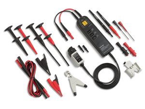
Early designs consisted of a pair of passive probes terminated at a differential amplifier located as a separate device adjacent to the oscilloscope. An alternate design placed the differential amplifier inside the probe body, but in the age of vacuum tube amplifiers, this was unwieldy. Currently, solid-state miniaturization permits the entire circuitry to sit in a reasonably compact differential probe body, which is cabled to a single analog channel input at the oscilloscope. Because there is only one signal path outside of the probe body, costly signal path matching is reduced. There is provision for a ground-return lead on the differential probe body, but this circuit is not required for most measurements.
Included with most differential probes is a variety of hardware, which facilitates probing closely spaced test points such as adjacent pins having differing spacings in integrated circuits. The whole thing is quite user-friendly once you get past the differential probe compensation process, which is outlined in the user manual.
To begin, connect the differential probe to one of the analog channel inputs and turn that channel on. Use the Y-lead adapter to connect to the probe compensation terminals, a square-wave source on the oscilloscope front panel that is used also for compensating passive probes. Then press Autoset to display a stable square wave.
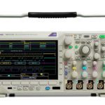
To continue the differential probe calibration, the oscilloscope should be warmed up for about 20 minutes, depending on the ambient temperature. In the Tektronix MDO3000 oscilloscope, from the utility menu, select Calibration. The pass should be displayed in the Status Box. If Pass is not displayed, back up and do a Signal-Path Compensation. For this, disconnect all probes and signal sources from the channel inputs and Select Calibrate. When Pass appears in the Status Box, once again connect the differential probe to the square wave source. From the vertical menu, select Probe Calibration. In the Probe Setup window, select Clear Probe Calibration and Calibrate Probe. The differential probe calibration is complete.
Following calibration, the differential probe is ready for use. The probe is protected against static voltage. But care must be taken to prevent the probe tip amplifier from damage from overvoltage.
The common-mode signal range refers to the maximum voltage with respect to ground that can be applied to either input without saturating the probe input circuitry. To test this common-mode voltage, set the probe range to 42 V, connect a probe input to ground and connect the other probe input to one of the differential signal outputs. Perform the test separately with each differential signal output.
Because of the electrical environment within which they are used, differential probes in some applications are required to have higher voltage ratings, typically 600 V. The price range is around $350 to over $5,000. These probes come in various sizes, the smaller ones characterized by higher bandwidth. The larger sizes, while less portable, have higher voltage ranges and greater portability. With 30-ft cable, the larger probe can be placed at some distance from the oscilloscope. The probe housing is sometimes filled with dielectric oil for high-voltage stability.

Hey David, nice overview of probes. As signals get faster, we see more engineers needing the capabilities provided by active broadband probes, such as the Rohde&Schwarz RT-ZSxx and RT-ZDxx probes.
While high input impedance and low capacitive loading are important specifications for these types of probes, you also need to consider other performance specifications, such as noise and linearity. Low noise allows you to make more accurate measurements, while high linearity is especially important when performing FFT analyses on high-frequency signals.
Worth adding is that one of the cool things about the latest generation of oscilloscopes is that you can add digital logic capability to them and still keep costs down. For example, you can add up to eight digital inputs to Rohde&Schwarz’s RTC 1000 Series.
This capability can come in handy if you’re designing or troubleshooting embedded systems. For example, you can trigger on a combination of the logic inputs and see what an analog output is doing. Adding digital logic capability also lets the scope do serial protocol analysis and troubleshoot problems with I2C, SPI, UART/RS-232/ RS-422/RS-485, CAN, and LIN buses.
So can we use a differential probe to measure a signal with reference to ground instead of using passive probe? Is there any side impact?
Curious why no one ever built a infrared active probe for our scopes? This can omit impedence issues and not to mention all the cables from our test benches… food for thought!