Amplitude distortion is the unintended modification of a signal, typically while undergoing amplification. Amplitude modulation, in contrast, is the intended modification of a carrier wave in response to a varying audio, video or other information-bearing signal.
Sources of amplitude distortion include noise and interference, but the main source is non-linear amplification. Amplitude distortion can include noise sources superimposed on the waveform of interest. An example is 60 Hz power line hum from a defective power supply. Another source of amplitude distortion is intermodulation distortion, when two signals X and Y mix to form the products X + Y, X – Y, 2X – Y, 2Y – X, and so on.
The kind of amplitude distortion that probably gets the most discussion is that due to amplification problems. An amplifier generally requires some form of dc bias on its input so the amplifier can amplify the input signal over its entire positive and negative excursion. The correct dc input bias will give a Class-A type amplification so long as the input doesn’t exceed the maximum level the amplifier can handle.
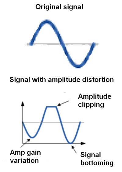
When the input signal exceeds the maximum capacity of the amplifier (i.e. the input is over-driven), the output voltage signal becomes clipped in both the positive and negative excursions of the waveform. This type of amplitude distortion is called clipping.
A sufficiently large input amplitude causes substantial clipping and forces the peak and trough parts of the waveform to be flattened or clipped-off. Of course, increasing the clipping on a sinusoid will eventually produce an output waveform resembling a square wave. This fact is sometimes used to synthesize square waves for use by digital circuitry. And, some rock bands actually prefer the highly distorted sounds of clipped waveforms.
Input amplifier bias problems are the second major cause of amplitude clipping. Specifically, clipping can be the result of the biasing Q-point set at the wrong position on the load line. If the input biasing point is correct, the output waveform should have the same shape as that of the input waveform only bigger. If the dc bias is too low the Q-point will lie in the lower half of the load line. Then the output waveform will have its negative half clipped. Too much dc bias will locate the Q-point in the upper half of the load line and produce clipping in the positive half of the output waveform.

Also, a bias voltage that is set too low will cause the amp to not fully conduct during the negative half of the cycle. So the output is set by the supply voltage in this case. When the bias is too high, the positive half of the cycle saturates the amp and the output drops almost to zero.
Amplitude distortion greatly reduces the amplifier efficiency in that the flat tops of the distorted output waveform do not contribute anything to the strength of the output signal.
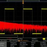
That said, distortion, separate from other sources of distortion, is typically measured only during debugging procedures when there is a problem with the input amplifier. Then it may be possible to eyeball clipping or other amplitude problems on a scope time-based display. However, the more typical measurement technique is to simply look at the output waveform on a frequency-mode FFT display or with a THD (total harmonic distortion) meter. The reason is that amplitude clipping and other amplitude distortion problems add frequency content to the fundamental waveform. The extra frequencies show up in these displays. That said, it may be difficult to distinguish frequencies caused by amplitude distortion from other frequencies in the output caused by other problems such as frequency or phase distortions.

Leave a Reply
You must be logged in to post a comment.