Interferometers figure prominently in the history of experimental physics. They were at the heart of the Michelson-Morley Experiment of 1887 that attempted unsuccessfully to detect the existence of an ether wind, a hypothetical medium for light transmission. (The null result was not because of any inadequacy in the instrumentation or deficiency in the design of the experiment, nor lack of energy and patience of the experimenters.) Interferometers are also at the heart of the recent successful first-ever detection of extremely faint gravitational waves.
The interferometer, as invented by Albert Michelson, is a simple instrument capable of displaying precise information concerning the phase relation of two light paths, and by extension, their speed and/or the distance they have traveled. Any difference in the speed/distance would indicate a distortion in spacetime caused by the arrival of gravitational waves.
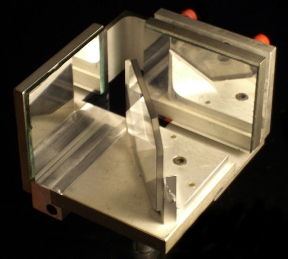
 Michelson’s original interferometer consisted of two perpendicular arms. A beam splitter, consisting of a half-silvered mirror, divided light directed toward it into the two separate perpendicular paths. These beams reflect back. Any difference in speed or distance traversed translates into a slight phase difference and accordingly an interference pattern, which may be easily seen and measured.
Michelson and Morley were surprised and baffled when they detected no speed difference in the beams of light. That the two light beams had the same speed indicated that the apparent speed of light was not influenced by motion of the observer, carried along on earth hurtling at great velocity through space.
Despite the null result in this particular experiment, the interferometer has endured as a measuring instrument and has been used successfully in a great many applications. Currently, after numerous attempts, the interferometer has been used to detect, for the first time, the presence of gravitational waves, with profound implications in the field of astrophysics.
Gravitational waves as received on earth are incredibly faint because the force of gravity itself is weaker than the other forces in nature. Moreover, the source — interacting black holes — is distant. For this reason, previous attempts to detect gravitational waves have not succeeded.
The sensitivity of an interferometer can be increased by making the arms longer. Another strategy is to isolate the instrument from spurious inputs such as ambient vibration and electronic noise.
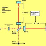
The recent detection of gravitational waves using interferometers happened at the Laser Interferometer Gravitational-Wave Observatory (LIGO). Begun in 1992, this large array of instrumentation is an ambitious experiment designed to detect gravitational waves at two locations remote from one another. One is in Livingston, La., and the other is in Hanford, Wash. To differentiate gravitational waves from the many possible spurious signals and ever-present background noise, outputs from the two facilities are continuously compared.
Each facility has a pair of 2.5-mile perpendicular arms, which are airtight cylinders sized to contain up to five interferometers within an ultra-high vacuum. Depending on the direction of the source, genuine signals should be microseconds apart and they should exhibit the same wave signature. This is precisely what happened on September 14, 2015 when gravitational waves from two enormous black holes merged at a distance in time and space of about 1.3 billion light years from earth.
This enormously energetic event, as predicted by Einstein’s General Theory of Relativity, caused minute differences in length of the interferometer arms at both LIGO facilities, with identical waveform displays. It has been stated that detection of gravitational waves will give us a new way to listen to the universe, and from this, knowledge will ultimately be acquired concerning the first fraction of a second of existence.
In general, interferometers can be categorized in terms of several criteria. Conventional heterodyne receivers are considered a type of interferometer because they nonlinearly combine input signals into new frequencies sometimes called heterodynes. A related type of interferometer is called the homodyne where there is interference between two beams at the same wavelength (or carrier frequency). The phase difference between the two beams results in a change in the intensity of the light on the detector. The resulting intensity of the light after mixing of these two beams is measured, or the pattern of interference fringes is viewed or recorded.
 Michelson’s interferometer is considered a double-path interferometer because the reference beam and sample beam travel along divergent paths. In contrast, a common path interferometer is one in which the reference beam and sample beam travel along the same path. Fiber optic gyroscopes are an example.
Another type of interferometer is the wavefront-splitting type which divides a light wavefront emerging from a point or a narrow slit (i.e. spatially coherent light). After the two parts of the wavefront travel through different paths, they recombine. Young’s interference experiment, which helped prove the wave nature of light, is an example.
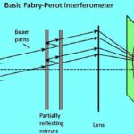
In contrast, Michelson’s device is a type of amplitude-splitting interferometer because it uses a partial reflector to divide the amplitude of the incident wave into separate beams which are separated and recombined. Another example is that of the Fabry–Pérot interferometer which has a pair of partially silvered glass optical flats spaced several millimeters to centimeters apart with the silvered surfaces facing each other.

Leave a Reply
You must be logged in to post a comment.