Industrial measurements often must take place via specialized transducers sized specifically for the current and voltage swings involved.
Will Delsman | NK Technologies
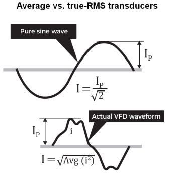
Older ammeters worked great when the current flowed at a steady 50 or 60 Hz. Consider the antique GE model 8AK1A1AF. I have one that remains accurate after decades of use and misuse. The nameplate shows “60 Hertz,” denoting its limited scope of applications. Try to get an accurate reading when there is much distortion to the current sine wave shape or if the frequency is anything other than 60 hertz and you are in for a frustrating experience.
Back in the dark ages, test equipment like this old beast utilized a current transformer design based on a toroid. The metal jaws surrounding the conductor were wrapped with many turns of thin copper wire. The magnetic field produced by the ac current caused a voltage to be generated in the wraps, and this small voltage would drive the pointer to display the amount of current present.
There was no simple method to detect or measure dc current beyond current shunts.
Present-day ammeters are most often now designed to use hall-effect elements rather than toroids and can accurately measure ac or dc current. The output from the hall element is conditioned to produce an output proportional to the RMS current regardless of the amount of distortion or harmonic component in the monitored circuit.
Test vs. permanent monitoring
Test equipment like handheld ammeters and voltmeters are essential tools, but few have the ability to transmit the readings to a remote location or to store the measurement data for later review. And these abilities are usually necessary for industrial data collection. Usually it is a permanently installed device, known to the trade as a transducer or transmitter, that monitors industrial parameters and produces an output which can be stored at the site or uploaded to a cloud service. These sensors produce an output which is typically connected to and read by a panel meter, HMI, programmable controller, or data acquisition system.
Generally, industrial transducers must be installed in a cabinet for protection against the surrounding environment conditions while also providing a degree of safety against electrical shock and arc flash. These transducers are designed to be as compact as possible and have mounting options that include snapping onto a DIN rail or mounting with screws to a panel.
The current levels involved in many industrial settings are high enough to make the use of current-sensing resistors impractical or ill advised because of thermal issues. Instead, industrial current-measurement sensors typically use induction or Hall effect devices that entail no direct connection to the circuit. These types of devices must have an aperture or sensing window large enough to allow the monitored conductor to pass through easily, and be approved by a third party test lab to be safe when used with the relatively high current and voltage levels that characterize industrial processes.
Continuous voltage measurement
Use of one-piece current and voltage transducers helps keep the necessary panel space at a minimum. In the not too distant past, the production of a signal representing the line-to-line ac voltage–which could be read by a device like a chart recorder–required a high-accuracy ratiometric potential transformer (PT) and a separate “tin can” signal conditioner. The lower voltage from the PT (usually 120 Vac) rose and fell with the line voltage, and the signal conditioner converted the PT secondary to dc milliamps or low-voltage dc. The resulting signal from the conditioner would go to the chart recorder. The resulting changes in the line voltage were graphed by colored ink from pens mounted over a revolving paper circle or long strip of paper. Set up took a steady hand for positioning the pens so they just touch the paper, and the chart recorder had to be well isolated from vibration or the lines could be shaky and inaccurate.
Today, voltage transducers are quite small, even those designed to measure up to 1,500 V. But potentials exceeding this level still need the PT/conditioner approach. Updated designs require two wires for measuring potential, a low-voltage power supply, and two wires carrying the output signal to a data acquisition system, essentially an electronic chart recorder. The measurement data can be read on a display immediately, and the chart can be printed for a permanent physical record. There are no errors from vibration or improper pen installation, and pixels do not run out of ink. In addition, there are fewer components, fewer connections, and less labor to install and calibrate.
Current measurements have followed a similar progression. In times past, a current transformer (CT) was installed and its secondary connected to the conditioner. The signal conditioner would mount a short distance from the installation point to keep the burden on the CT secondary at a minimum for better accuracy. A shorting block would be installed between the CT and signal conditioner. In the event the conditioner had to be taken out of service, this extra step allowed the CT secondary to stay closed while the monitored circuit current continued to power its load. The shorting block was necessary because a CT should never be energized if the secondary is open, with no load connected, as doing so is quite dangerous.
In the same physical space as the ancient CT, a modern one-piece current transducer eliminates the issue of CT-to-conditioner distance, as the two pieces are fractions of an inch apart inside the sensor housing. There is no need for a shorting block as it would be highly unlikely that the CT could separate from its printed circuit boards. There are also no dangerous voltages present between the sensor terminals when there is no load connected to the transducer. The present-day approach is extremely simple, uses two leads for power and either the same pair or two other wires to carry the output signal. This approach is much safer and reduces the number of connection points significantly. Simplicity can be counted on to improve overall reliability.
And of course, it is safer to use test equipment for troubleshooting the data acquisition system than for testing the primary, measured circuit. The sensor outputs are at a much lower voltage, but testing must still take place while the monitored circuit is energized to confirm the accuracy of sensor output.

When the transducer output produces a “live zero” as with a 4-20 mA output, the 4 mA can be read with many multi-meters on the low dc current setting by simply disconnecting the transducer output at the load (panel meter, PLC, etc.), and connecting the test leads in series between the output and the load. The sensor output will still read 4 mA if the rest of the connections remain in place, including the power supply to the sensor.
Scaling test
When troubleshooting a transducer, regardless of what property the transducer will measure, make sure to understand what the output should be for a given amount of the measured property. We will use a current transducer as an example:
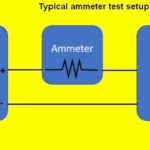
Use an ammeter to see how much current gets delivered to the load.
Check the current transducer range to ascertain how much current constitutes the maximum output from the transducer.
Calculate the expected sensor output. For example, suppose a transducer produces 10 Vdc when current rises to 50 A. Divide the output (10 Vdc) by the range: 10/50 or 1/5. So there is 1 V of output signal for every 5 A used. Thus 25 A will create a 5-Vdc output. Another way to arrive at the correct answer: Take the reading from the hand ammeter and divide it by the range, 25/50 = 0.50. Then use that result to show the transducer output: 10 x 0.5 = 5 Vdc. Half the range value will produce half the output value. Thus if the current measured is 37.50 A, multiply by 0.20 and verify that the transducer output is 7.5 V.
The same approach is used when the transducer has the “live-zero” output, but the output signal when there is zero current (or voltage, or whatever you are measuring) must be included in the calculation. This is referred to as signal offset.
With any analog signal produced by a transducer or transmitter, the device receiving the output (data acquisition system, panel display, PLC, etc.) must be set up so it understands what the output means. For example, a 4-20 mA transducer signal produces a range of 16 mA (20-4). Since the example above describes a 0-50 range, the relationship is 16/50 or 0.32 mA/A. A load of 37.50 A causes a change in the transducer output of 12 mA (0.32×37.50). So, with the signal offset value added, the transducer output should be 12 mA + 4 mA = 16 mA.
If the need is for benchtop measurements, there are many choices available for ac or dc circuits, current and voltage. If, on the other hand, the need is to store and analyze these measurements, a more permanently installed transducer set will be the best solution.

Leave a Reply
You must be logged in to post a comment.