Early analog oscilloscopes had a vast number of front panel controls, mostly knobs that had to be endlessly twirled and tweaked to obtain and maintain stable waveforms on the screen. In the modern digital instrument with a flat screen, there is no focus knob, as required for the CRT with its beam of electrons traveling the length of the tube.

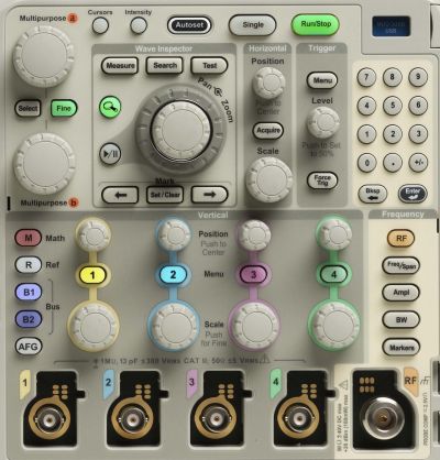
Our contemporary digital oscilloscope has far fewer front-panel controls. It typically employs multipurpose knobs that are contextual, performing multiple tasks depending on the menu item that is active. Many of the buttons have diverse functions as well, or serve only to open a menu that appears across the bottom of the display.
A row of soft keys (this is industry-wide terminology) activate menu selections, which vary depending upon the operation that has been chosen by the user. Most major digital storage oscilloscope models have similar controls. Here is a survey of those in a typical contemporary instrument:
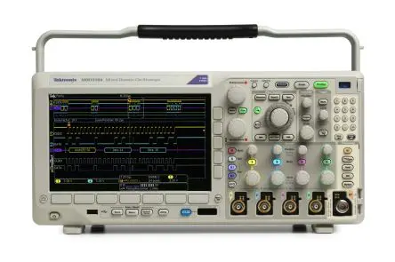
The menu system consists of a front-panel menu button that, when pressed, displays a menu for the desired function. For example, if the Math button has been pressed while one or more of the analog input channels is active, the Math menu appears across the bottom of the display. The available menu selections are Dual Waveform Math, FFT, Advanced Math, Label and Auto-Scale. Each of these selections has an associated soft key directly below it.
If the soft key that is directly below Dual Waveform Math is pressed, the applicable vertical submenu appears to the right of the display, each item, in turn, having an associated soft key. Dual Waveform Math, as its name implies, performs any of the four basic arithmetic operations — add, subtract, multiply and divide — on any of two waveforms that are present at the analog inputs or reference channels. These are labeled First Source and Second Source, and may be chosen by turning the aptly-named Multipurpose Knobs a and b. The operator, add, subtract, multiply or divide, may be chosen by toggling the associated soft key. Instantly, the math waveform appears, in its dedicated red color.
Notice that if there is no probe or BNC cable connnected to an analog input channel, there is still a signal/waveform present. It just happens to have a zero-volt amplitude. Accordingly, the math operations can be and are performed.
The next selection in the horizontal math menu is the very frequently used FFT. Pressing the associated soft key brings up the vertical FFT menu. For this transform, only a single input is used, one of the four analog channel inputs or one of the four reference channels. It is selected merely by turning Multipurpose Knob a. Then press Menu Off to get a clear view of the display. Notice that the original analog or reference waveform is shown in the time domain along with the frequency domain display. In an MDO instrument, they are shown in split-screen format, which is why the instrument is known as a mixed-domain oscilloscope. The same signal is shown in two domains as opposed to in an MSO or mixed-signal oscilloscope, where separate signals from different analog or reference channels are displayed together.
The next menu selection is Advanced Math. Using Multipurpose Knob a, the appropriate analog or reference channel can be selected and chosen by pressing the soft key associated with Enter Selection. Then, again using Multipurpose Knob a, choose OK Accept, or select Cancel by pressing Menu Off.
After toggling Math Off, the Reference button opens the Reference Menu across the bottom of the display. Reference waveforms may be created and displayed for a variety of purposes such as setting up a standard against which to compare other wavforms.
Press Reference to bring up the horizontal Reference menu. This allows waveforms to be entered (time and date stamped) and recalled, whereupon they are displaced in the dedicated reference color, white. These Reference waveforms are nonvolatile, which means they are retained when the oscilloscope is defaulted or power-cycled.
The lower horizontal soft keys permit individual Reference waveforms to be toggled on and off. When one or more is on, the vertical side menu appears. Then vertical and horizontal settings may be adjusted, labels applied, Reference details acquired and waveforms may be saved to external storage such as to a flash drive inserted into a USB slot.
The front panel button labeled AFG permits the user to display on either any analog channel, or on the RF channel, any of the arbitrary function generator waveforms stored in the oscilloscope. To display them, a BNC cable must be run from AFG Out on the rear panel to the appropriate port on the front panel, and this channel must be turned on. An AFG waveform is selected by pressing the soft key associated with Waveform in the lower horizontal AFG menu. Pressing Waveform Settings, frequency/period, amplitude and offset are chosen. The auxiliary output on the rear panel can be set at Main Trigger, Event or AFG.
The analog channel buttons are quite important. In addition to allowing you to turn on one or more analog channels, when pressed they cause a horizontal menu to appear across the bottom. Selections are coupling, termination, invert, bandwidth, label, fine scale, offset, position, probe setup and deskew.
Coupling may be ac or dc. The default is dc and this is used most of the time. It should really be called ac/dc. It displays the ac waveform plus any dc component on which the waveform may be riding. AC eliminates the dc component. It is used when the dc is relatively high so that the ac component cannot be accurately displayed thanks to Autoset. AC may be employed to accurately characterize ripple in the output of a dc power supply.
Termination is one Megohm or 50 Ω. One Megohm is the default, and it is used almost all the time. It resembles a high-impedance multimeter, which tends not to load the circuit under investigation. The 50-Ω termination is used only with a low-amplitude signal when necessary to match impedance for the purpose of getting an accurate reading. It must be used with great care so as not to overload the oscilloscope or circuit.
Invert is normally left off. When turned on, it reverses the signal’s polarity. The effect may be seen by toggling it with a sine wave from the AFG displayed.
Bandwidth is normally kept at full, the default. It is used to reduce the bandwidth so as to limit noise, a high-bandwidth phenomenon.
The Acquire button brings up the horizontal Acquisition Menu, which is comprised of several important selections. Pressing the soft key associated with Mode permits the user to choose among five sampling modes. Sample, the default, is used most of the time. Peak Detect and High resolution make use of sample points that are discarded at lower sweep speeds. They operate only when the sample rate is below the maximum. The sample rate is determined by setting the horizontal scale in conjunction with the record length.
Record length is quantified in terms of number of points. It is set by turning Multipurpose Knob a, and may be one thousand, ten thousand, one hundred thousand, one million, five million or ten million.
FastAcq pertains to the way in which the waveform palette is displayed. It may be represented as temperature or spectrum, and it may be normal or inverted. These choices are made by turning Multipurpose Knob a.
Delay may be toggled on or off. Its effect may be observed by turning on AFG and observing the sine wave as Delay is toggled.
The effect of Horizontal Position may be observed by pressing the associated soft key and turning Multipurpose Knob a.
Waveform Display, Dots Only and Persistence, can be turned on or off and Persist Time may be set by turning Multipurpose Knob a, or it may be set to Automatic.
XY Display may be turned off (the default) or set to Triggered XY, displaying the Lissajous pattern.
The Trigger Menu button permits the user to select triggering options. Type includes Edge, Sequence (B Trigger), Pulse Width, Timeout, Runt, Logic, Setup and Hold and Rise/Fall Time. Trigger Coupling may be dc, ac, High-Frequency Reject, Low Frequency and Noise Reject (dc Low-Frequency Sensitivity). Mode may be Auto or Holdoff. Holdoff inhibits triggering until a user-chosen amount of time elapses and another triggering event occurs. Its purpose is to prevent false triggering if there is an anomalous spike.

Leave a Reply
You must be logged in to post a comment.