Engineers know what an oscilloscope probe is. It basically permits the user to measure the voltage at any terminal or wire and display the waveform. It usually incorporates a needle point that is capable of getting into a tight place without shorting out to another pin, wire or grounded surface. And it can be equipped with various accessories for special situations, such as the useful hook tip, a spring-loaded attachment that clips onto the wire or terminal of interest and remains in place.

The probe tip extends from the end of the insulated probe body, which serves as a handle and also contains components and circuitry specific to the probe type. Emerging from the other end of the probe body is a BNC cable that connects to an analog channel input and carries the signal to the oscilloscope. Also coming out of the probe body is the ground return lead, equipped with an alligator clip.
The most common oscilloscope probe is the 10:1 passive probe, which is perfect for most applications. The 10:1 designation indicates that the probe attenuates the signal by a factor of 10. A probe of a 100-V signal causes 10 V to appear at the oscilloscope input. In most instruments, the oscilloscope senses the probe attenuation and displays the actual voltage at the DUI output. Not all oscilloscopes perform this calculation, however, and this is something that is easily checked by probing a known voltage and pressing Measure on the oscilloscope front panel. (A 1:10 probe amplifies the DUI voltage, and should be used with caution to avoid overloading the oscilloscope.) A passive probe contains no active components and requires no external power. An active probe is far more expensive, has a much lower voltage rating, and is easily damaged, even in handling due to static discharge. It is used only in special applications.
Some passive probes are switchable. There is a slide switch on the probe body which allows the user to choose 10:1 or 1:1 attenuation. This probe has reduced bandwidth and it is possible to overload the oscilloscope if the switch is left in the wrong position, so generally the switchable probe is not recommended.
Oscilloscope manufacturers normally supply the same number of 10:1 passive probes as there are analog channels in the instrument, usually two or four. Perhaps the most important reason is that each probe is compensated to a specific channel and thereafter should be used exclusively with that channel. The manufacturer supplies colored rings that match the dedicated analog channel colors so the proper compensated probe can be selected for each channel. All this is necessary because, due to internal wiring layout and other factors, specific channels may have slightly different LC reactances. Probe qualities must be such as not to distort the signal under investigation. This becomes increasingly important in high-bandwidth instruments and when measuring high-frequency signals.
Compensating probes is a simple process. Details are in the user manual. The basic idea is that terminals on the front panel provide a square wave. Using its alligator clip, connect the ground-return lead to the terminal marked Ground, and using the hook tip, connect the probe tip to the other terminal so that the square wave is displayed in the channel to which the probe is to be compensated. In the probe body is a slotted screw which can be adjusted to make a perfect square wave with a flat top and square corners. Repeat for each probe-channel combination, labeling the probes as you go. (A point to note is that there are instructions for do-it-yourself probes online that do not include a compensation network.)
For example, the procedure to compensate the Tektronix TPP0250, 0500 or 1000 passive voltage probe is simple because it is automatic. The 10:1 passive probe with the adjustment on the probe body incorporates a trimmer capacitor that takes care of the inductive/capacitive reactance. To compensate the Tektronix TPP0250, 0500 or 1000 passive voltage probe, the procedure is simple because it is automatic. In the widely used Tektronix TPP1000 probe, compensation takes place within the oscilloscope, where all settings are stored. When used on an MDO3000 Series Oscilloscope, compensation generates values for a specific probe and channel combination. Move the probe to another channel and you’ll need to perform the compensation procedure for the new combination.
A point to note is that probe impedance varies with the frequency of the signal being measured, even for compensated probes. At low frequencies, the impedance of a typical passive probe is 10 MΩ. At 1 MHz, impedance drops to about 17.4 kΩ. At 100 MHz, it is below 200 Ω. Also note that any lead added to the probe tip or the ground wire adds inductance, and lead inductance can add overshoot and ringing to the signal seen on the scope display.
The probe lead length itself adds some inductive loading to the input ground leads. The inductance of the ground lead and input lead combine with the probe input capacitance to form a series LC network whose impedance drops substantially at its resonant frequency. This effect, known as ground lead corruption, causes the ringing often seen after the leading edge of pulses. The only realistic option for reducing this ringing is to keep input and ground leads as short as possible, thereby keeping inductance as low as possible.
Especially for a bench-type and rack or cart mounted oscilloscope, the probe cable must be long enough for the user to move the probe tip to the various locations of interest. Generally, the probe cable is less than a meter long so its length doesn’t affect the bandwidth excessively. Similarly, the ground return lead should be as short as possible and kept straight. At high frequencies, even a slight bend is equivalent to a fractional turn in an inductive coil, and the increased inductive reactance equates to greater than intended attenuation.
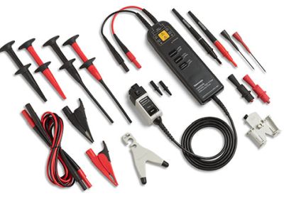
Differential signal measurements involve probing of two signal lines, both of which are referenced to but float above ground potential. This is not like probing the positive and negative terminals, for example, of a 9-V dry cell. These terminals float separately from, but are not referenced to, the ac system ground to which the oscilloscope non-current carrying conductive parts are bonded.
Examples of where the differential measurement is necessary include grounded three-phase power systems, switching power supplies and variable frequency motor drives. Differential measurements cannot take place on a grounded, bench-type oscilloscope by simply touching the probe tip to one line and the ground reference lead to the other line. To do so would cause a heavy fault current in the equipment under investigation to flow from the ground reference lead and signal path inside the oscilloscope. The reason is because the instrument is connected via the equipment-grounding conductor back to the electrical system ground at the electrical service.
There are four possible remedies. One has its own hazards and a National Electrical Code violation. Another can result in possible inaccurate measurements. A third is safe and accurate but expensive.
Unfortunately, the remedy frequently encountered is to saw off the ground prong in the power cord plug. This un-grounds the oscilloscope so there is no ground-fault when the ground-return lead touches the line referenced to but floating above ground potential. This solution introduces another hazard: Because the oscilloscope is no longer grounded, an internal fault can energize non-current-carrying metal parts such as the analog and RF input sockets. The same situation exists if you power the oscilloscope through an isolation transformer.
Each signal line can be acquired on a separate oscilloscope channel and, using Waveform Math, the two channels can be algebraically summed. This procedure works if properly performed and is not hazardous. But accuracy can be compromised because the two signal lines may be not perfectly matched.
Differential probes can perform well in substantially reducing the common-mode rejection ratio and eliminating the ground-fault hazard. They may, however, reduce bandwidth and are expensive.
A hand-held, battery-powered oscilloscope has channel inputs that are insulated from ground and, in most models, from each other. This eliminates the ground-fault hazard, but the hand-held model does not have all the features, analytic capabilities and the large screen of a bench-type model. Most users find it the best solution for servicing three-phase systems and variable-frequency motor drives provided voltage limits are not exceeded.

Leave a Reply
You must be logged in to post a comment.