Discussions of signal jamming were once largely confined to electronic warfare forums. But with the rise of autonomous vehicle technology, jamming has become a mainstream topic. It now pays to know a few basics about both the test setups necessary to gauge resistance to jamming techniques and the principles of signal propagation. Many of the sophisticated advances in signal jamming arose from work with radar. So it is useful to start with a review of a few radar fundamentals.
The idea of radar, of course, is that a target reflects some of the energy of a transmitted signal. The returned energy is received and processed to detect the target and extract its location and relative velocity. The direction of arrival of the returned signal can also reveal the angular position of the target if the original antenna beam is narrow enough. And if there is relative motion between the target and radar, the shift in the carrier frequency of the reflected wave (i.e. the Doppler effect) is a measure of the relative radial velocity of the target that can be used to distinguish moving targets from stationary objects.
Typical radar transmitters emit signals in the form of pulses. And the pulses generally have a low duty cycle where the duty cycle is the ratio of pulse duration over a pulse period. Moreover, the resolution of radar (and for that matter, lidar) is limited by the pulse width. For example, a 1-μsec pulse spans 150 m in space, so a radar emitting 1-μsec pulses can’t resolve distances less than 150 m.
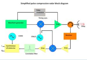
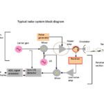
That said, chirp modulation is a method used to improve the distance resolution of a radar signal to better than 1/(pulse width). A chirp is a signal whose frequency rises or falls with time. There are several kinds of chirps — linear, nonlinear, exponential, etc. Some systems also emit a compressed pulse in the interest of reducing transmitter power and the possibility of interception. All in all, the subject becomes complex quickly. Thus a chirp radar includes stages that modulate the transmitted pulse, transmit it, receive the echo, and then correlate the received signal with the transmitted pulse.
There is a potential ambiguity when energy returns from a distant target after the radar has already emitted a second pulse. This is called a second-time-around echo. To measure far-away objects unambiguously, the radar must wait for their pulses to return. However, the fastest object the radar can unambiguously measure is determined by the emitted pulse rate, i.e. pulse repetition frequency. To measure the speed of fast objects, the PRF must be high, hence there is a tradeoff between radar range and speed detection.
A point to note is that a radar jammer often has a range advantage over the radar it targets. That’s because signals from the jammer to the radar all see a 1/R2 path loss, while the radar return will see a 1/R4 loss because it is bouncing back from a target.
With these points in mind, consider the various types of radar jamming methods as defined in electronic warfare. Barrage jammers attempt to overwhelm the radar receiver with an interfering signal in the received frequency band. Noise jammers modulate the jamming signal with AM or phase noise. Deceptive jammers use either a repeater or a memory to produce a replica of a radar return with appropriate modifications in time or frequency. Repeater jammers modify and retransmit received radar signals so the resulting echo relays inaccurate position. Similarly, a transponder jammer is a repeater that plays back a stored replica of the signal after being triggered by the reception of the radar signal.
A related mode is set-on jamming where a receiver measures the threat radar frequency and adjusts an oscillator to retransmit it. Ditto for a swept-spot jammer, one that sweeps an oscillator over a band of frequencies used by the radar receiver. Finally, there are a couple of electronic-warfare terms that apply to military maneuvers. A stand-off jammer is usually an aircraft that stays safely away from hostile weapons when jamming radar for the attacking planes and aircraft, while a stand-in jammer does the same thing while being close enough to take on hostile fire.
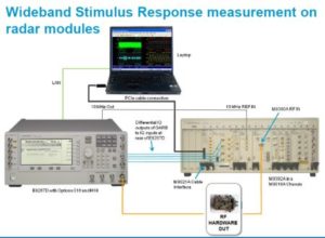
Anti-jamming techniques often attempt to thwart these efforts by measures that include varying the radar pulse timing patterns. But timing properties may also be varied depending on the radar mode (search, acquisition, track). Additionally, adjusting the pulse timing lets the radar gauge the target’s unambiguous range and speeds. In both radar development and anti-jamming, the emphasis is on simulating the radar or anti-jamming setup with test instrumentation prior before committing to a hardware or software design.
A frequent approach is to synthesize the complex chirp and pulse modulation waveforms on a tool such as Matlab, then feed the information to an arbitrary waveform generator to actually build the waveform. There are also specialized software packages for waveform building such as Signal Studio from Keysight Technologies.
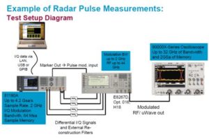
In test setups, the waveform generator is typically also used to add real-world effects to the signal stream such as jitter and wobulation, a change in the pulse repetition rate and center frequency. Pulse-building software can as well add effects that arise from specific antenna patterns and radiation qualities.
Moreover, modern test instruments often incorporate multiple functions that ease the task of creating a bench-instrument-based radar signal. For example, it is possible to find high-end signal analyzers that incorporate swept-spectrum analysis, FFT analysis, an RF and baseband vector signal analyzer, and a noise figure analyzer.


Leave a Reply
You must be logged in to post a comment.