When a piece of equipment turns up completely dead, one of the first things to look at is the power supply. If using an oscilloscope for this sort of troubleshooting, it should be a hand-held, battery-powered instrument isolated from ground, at least at the outset. The reason is there may be internal voltages that are referenced to but float above ground, a condition which can create hazardous fault currents if connected to a bench-type oscilloscope. This is especially true of switch-mode power supplies (SMPS), where both sides of the circuit float above ground.
In the SMPS, a number of configurations are possible, most notably buck, boost and inverting buck-boost. In each of these, the MOSFET is the master mind. It does the switching while the diode determines the direction in which the charge carriers flow and inductors and capacitors store electrical energy. The SMPS regulates at the output by continuously varying the duty cycle, as opposed to the linear power supply, which regulates the output by making changes as needed by adjusting the amount of power that is dissipated.
An SMPS buck converter is analogous to a linear power supply with a step-down transformer. When the switch is closed, voltage is applied across the inductor. When the switch is open, current through the inductor continues to flow. Feedback controls pulse width at constant repetition rate or it controls repetition rate at constant pulse width.
An SMPS boost converter is analogous to a linear power supply with a step-up transformer. When the switch is closed, inductor current increases. When the switch turns off, voltage spikes as the inductor attempts to maintain constant current, which it cannot do since the inductor is using all available energy to construct its magnetic field. At this juncture, the diode conducts and current from the inductor flows into the capacitor. This accounts for the higher output voltage with respect to the input.
In an SMPS, a transistor driven into its saturated region periodically applies the unregulated dc at the input to an inductor, which functions as a storage device. During each pulse, its magnetic field increases until the switch is turned off. Then the stored energy is filtered. A voltage reference is compared with the output in a feedback loop, changing the pulse width or frequency. The SMPS can work with an ac line frequency input or with an unregulated dc input.
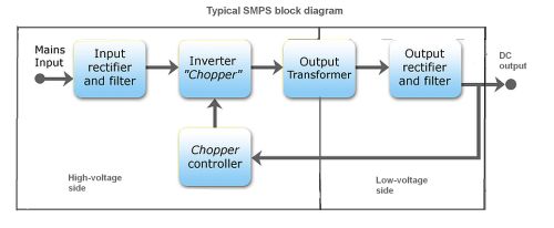 In a generic SMPS, mains power enters the supply through a line filter. Power is then rectified and smoothed into a high dc voltage (a few hundreds volts). One or more transistors (or MOSFETs) then switch this high dc voltage on and off to drive the primary of a transformer. (Though some SMPS topologies are transformerless.) The voltage is rectified and filtered on the secondary side of the transformer.
Output regulation takes place by switching the transistors via a control circuit that senses the output voltage (and input current) and adjusts the on and off times of the transistor accordingly. This control circuit is often on the primary side and may get its power from an extra winding on the transformer. A sample of the output voltage is typically fed back via an optocoupler. (Again, some SMPS designs implement feedback without using an optocoupler.) In some cases the control circuit sits on the secondary side and drives the switch via a small additional transformer.
A point to note is that SMPSs have high and low-voltage sides (primary and secondary sides). The transformer isolates the primary and secondary side. (Again, there are transformerless SMPS designs that do not implement isolation.) Often, if the ground of the output is not connected to the mains ground, a small high-voltage capacitor connects these two grounds at high frequency.
Because half the SMPS components directly connect to the mains voltage, there are dangerous voltages in the primary side of the supply. A large storage capacitor charges at high voltage and can retain a dangerous voltage even when the mains supply is disconnected. SMPSs frequently include bleeding resistors to dissipate this voltage, but these resistors could be broken so the capacitors could stay charged. Consequently, it’s best to discharge the capacitors through a suitable resistor (usually a few kiloohms) via insulated probes as on a multimeter. Then measure the voltage to ensure it’s zero before proceeding. Also keep in mind that heat sinks frequently are not grounded and may be at the mains voltage.
Similarly, verify all capacitors are discharged. Many faulty electrolytic capacitors become disfigured or balloon out. Other visual indicators include burned black resistors and components that smell burned, particularly the transformer. A transformer that smells burned may have shorted turns. If so, it is frequently better to just replace the SMPS.
Although it may sound obvious, the troubleshooting of a dead supply starts by looking at the mains fuse. A blown fuse usually implies numerous faulty components; a healthy fuse may mean a single component caused the problem.
The condition of the fuse is also useful. One that only slowly burned implies the failure was not catastrophic. A catastrophic fuse implies a big current that damaged numerous components. Unfortunately some fuses are filled with sand and obscure what happened.
One trick for the first test of a supply with a blown fuse is to temporarily replace the fuse with a light bulb. The bulb should have roughly the same power rating as the SMPS. This prevents more catastrophic failures and avoids the nuisance of repeatedly replacing fuses. If things are normal, the bulb should flash for a fraction of a second and then glow slightly. If there’s still a short circuit, the bulb will glow brightly– time to keep looking for the problem.
An open fuse signals that something went really wrong in the supply, perhaps a short circuit. Typical problems include shorted power transistors or rectifier diodes, especially in the primary. The diode function of a multimeter can help spot shorts. It may also be useful to find a datasheet for the regulator IC in the SMPS, if it uses one. Many SMPS have a schematic close to the reference designs reported in the datasheet.
If the fuse is good but there is no output, the inrush current limiter (an NTC) may be suspect. High-power resistors on the primary side should also be checked. If the resistor value doesn’t match its color code or schematic value, unsolder one terminal and remeasure. Replace with a new one if values don’t match.
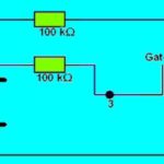
The first resistors to check are those in series with the power transistors. Sometimes the primary includes a high-value high-wattage resistor in series with a Zener diode. Check all diode junctions with the diode function of a multimeter. Regulator ICs can be faulty but usually not.
A dead power transistor increases the chances of other dead components. Often SMPSs include protection components such as an additional resistor or Zener diode to limit damage in a catastrophic failure.
One trick for checking the controller IC is to power it off-line with a small external dc power supply and check for pulses on the transistor base (or gate). But some ICs won’t work without a high voltage to switch, and the datasheet might mention this.
Another point to note is that dead semiconductors should be replaced with the exact same part. Alternatives are OK only if the original is unavailable or too expensive. For diodes, also check the switching time – replacement diodes should be at least as fast or faster than the old one. Similarly, replacement transistors should have similar gain and cut-off frequency. A rule of thumb is that the cut-off frequency should be at least ten times higher than the switching frequency. For MOSFETs, the gate capacitance should not exceed that of the old component, and the gate-threshold voltage should be close to that of the old device.
Sometimes the SMPS only partially works. It may start and then shut down, or it may pulsate trying to start every few seconds, or it may produce a wrong output voltage. It’s likely the power semiconductors are good, but the capacitors are suspect. Or there may be a problem with the feedback circuit.
One trick is to apply an external adjustable dc voltage to the SMPS output ensuring first that the SMPS is not connected to the mains. When the dc voltage increases gradually, the feedback circuit should work as the dc nears the nominal output voltage. There are no dangerous line voltages involved, so a scope can help diagnose the feedback circuit. Another technique is to supply the controller IC with the same low voltage source and examine what happens on the other side of the optocoupler.
Electrolytic capacitors frequently cause SMPS problems. Less expensive SMPS designs often have them working too close to their thermal dissipation limits. Their liquid electrolyte tends to evaporate and alter their operating qualities. Obviously, caps that are physically deformed are bad. But some can be bad and have no physical appearance issues. It’s helpful to just measure the capacitance, but a simple measurement is not enough. A better approach is to measure the equivalent series resistance (ESR) and compare it to that of a known-good capacitor. Unfortunately, this takes an ESR meter (or an RLC bridge). Electrolytic capacitors come in 85°C and 105°C versions. It’s prudent to choose the higher temperature if there is a choice.


I biilt a capacitive power supply unit and when it is powered with mains the 225k 450v ‘x’ rated capacitor ‘s output is only 1.8 – 2.0v . No fault is found in the capacitor or feed in resistor (100 ohm 1w) or bleeding resistor 470k . Pl. Help me to find the fault.
Thanks!