By David Herres
A vacuum-tube operational amplifier (op amp) was conceived in the early years of the Second World War and achieved great success as a means of directing artillery in conjunction with radar. In the decades that followed, implementation as a discrete semiconductor and IC integration, along with circuit refinements, have made the op amp a great industry workhorse in more peaceful, analog as well as digital applications.

The op amp is a differential amplifier, though not the only member of that useful class of devices. The fully differential amplifier has two outputs, while the op amp has one output and two inputs. The inputs, V+ and V–, are inverses of one another. The op amp amplifies only the difference between them. In the open-loop configuration, the degree of amplification is given by:
Vout = AOL (V+ – V–)
Where Vout is output voltage; V+ is non-inverting input; V– is inverting input; AOL is open-loop gain. In the open-loop configuration, there is no feedback in the external circuitry.
The degree of amplification is astronomical, frequently around 100,000. But applications are limited due to instability. The great advantage of the op amp becomes apparent when it is operated in the closed-loop mode. The amplification is far less, in accord with the following equation:
Vout = Vin (1 + Rf/Rg)

Where Rf and Rg are the values of feedback and ground resistors as specified in a schematic. This op amp is far more stable than the open-loop version. It solves stability and noise problems present in regenerative radio receivers and in long-distance phone communications in the mid twentieth century.
The 741 op amp is a widely used design first introduced in 1968. Still in production today, it carries enhancements over other op amps of the time that includes overload protection for both input and output. There is no latch-up when the common mode is exceeded, and the IC is notably free of oscillations.
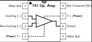 The 741 op amp can be used as either an inverting or a non-inverting amplifier. In an inverting mode, voltage is applied to pin two and the inverted output appears at pin six. In the non-inverting mode, the voltage is applied to pin three and non-inverted output appears likewise at pin six. This dual-mode capability in effect doubles the number of possible applications.

Leave a Reply
You must be logged in to post a comment.