By David Herres
Oscilloscopes typically display the amplitude of a signal on the Y axis as a function of time on the X axis. The resulting display can take the form of a straight horizontal line if it is a dc voltage, an irregular non-recurring and intermittent pattern for complex signals such as the human voice, or a continuous sine wave curve for simple periodic waveforms.
A pure sine wave is free of harmonics. All the energy is confined to a single frequency.
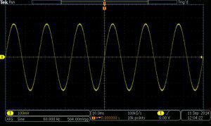 Consider the pure sine wave in the illustration from a Tektronix MDO3104 oscilloscope. It is derived from the scope’s internal function generator, set at 60 Hz. What is notable and also the defining characteristic of this sine wave is that the greater the amplitude as a positive or negative value, the slower the rate of change. Conversely, as the amplitude approaches zero on the Y axis, the greater (faster) the rate of change. This inverse relationship accounts for many of the properties of energy that fluctuates in a sine relationship.
For example, the rate-of-change property explains why the amount of current flowing through a capacitor is inversely proportional to the applied voltage. It likewise explains inductor qualities. For both these components, if there is no parasitic resistive component, the current is 90° out of phase with the voltage. Current leads voltage in a capacitor and lags voltage in an inductor.
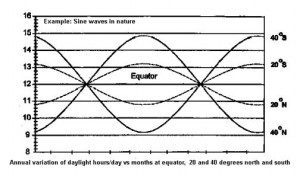 Many functions in nature conform to a sine wave. An example is the number of minutes of daylight lost or gained as plotted against the number of days elapsed since the longest or shortest day. The amount of daylight lost or gained is greatest midway between the longest and shortest day. Other examples of sine waves as they arise in the natural world include ocean waves and sound waves.
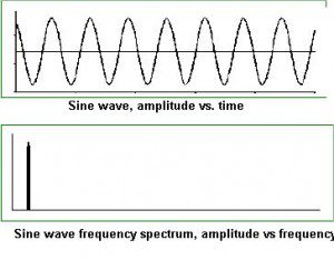 When a sine wave is superimposed on a second sine wave of the same frequency, phase and magnitude, the original signal retains its shape, unlike non-sinusoidal waveforms. Thus a sinewave is unique, which is why it plays a central role in Fourier analysis. The relationship becomes visible in the Tektronix 4000 series oscilloscopes where the waveform is simultaneously depicted in time and frequency domains.
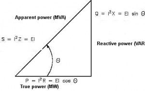 The electrical output in volts of an ac generator plotted against time conforms to the ubiquitous sine wave. That is because of the rotary nature of the generator. The relationship of apparent, real, and reactive power can be shown as a right triangle whose sides represent apparent power in units of megavolt amperes (MVA), real power units of megawatts (MW), and megavolt ampere reactive (MVAR) units representing reactive power. MVA is the square root of MW2+MVAR2 as in a right triangle.
An ac motor, induction or synchronous, works best when the waveform is a pure sine wave. The same is true of a transformer. The DC as produced by a solar PV array or other dc generators typically gets converted to ac through use of solid-state inverters capable of producing close approximations of sine waves. For co-generation with a utility, as in a grid-connected solar or wind system, a synchronous inverter is necessary to lock into the grid. Voltage, frequency and phase must match precisely.

Leave a Reply
You must be logged in to post a comment.