By David Herres
Unlike residential wiring, the electrical harness in an industrial or large commercial setting usually carries three-phase power. To many homeowners and beginning technologists, three-phase circuits are a big mystery only because they are unfamiliar. Actually they are simple, conceptually and in terms of the labor involved when working with three-phase equipment. Three-phase conductors are smaller, as are their raceways and over-current protection for three-phase circuits. Thus three-phase gear is easier to install than single-phase wiring.
There is one potential difficulty when contemplating a new three-phase installation: Three-phase power may not be available from the utility at the intended location. Usually three-phase distribution lines emanate from a substation and follow the main roads, downsizing to smaller single-phase lines for buildings that use less electrical power. When the utility extends a three-phase distribution line, it usually figures the customer should bear the cost.
A good way to get a sense of the distribution geometry is to drive around suburban areas looking at power lines and transformer arrays. (It is best to have someone else drive lest you hit a pole, altering the object by the act of observing it.) The three-phase service drop consists of three ungrounded (hot) conductors and a grounded neutral that terminate at a three-lug (plus ground) meter socket, and then go to the service entrance panel. This box consists of a neutral bar and three hot bus bars.
Three-pole breakers can plug into box positions to pick up three-phase power. Double-pole breakers can supply single-phase line-to-line loads and single-pole breakers can facilitate single-phase line-to-ground circuits.
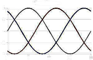
Thus, three-phase power lines can be divided in an entrance panel or load center to make single-phase power available. It is not possible, however, to change single-phase to three-phase power without use of a rotary or electronic phase converter. The reason is that the three conductors each carry alternating current voltages that are offset in time by one-third of the period. Specifically, the voltage on any conductor peaks at one third of a cycle after one of the other conductors and one third of a cycle before the third conductor. It is usually impractical to generate this kind of phase delay from a single-phase utility connection.
The connection of three-phase equipment sometimes involves special procedures. For example, this is the case for sizing the over-current protection of a three-phase synchronous or induction motor . Details are in the 2014 National Electrical Code, Article 430, Motors, Motor Circuits, and Controllers. Basically, the three conductors, without the neutral but with an equipment-grounding conductor, are brought to the motor terminals. The direction of rotation may be changed by reversing any two of the three wires. Phases may be balanced by rolling the connections (A to B, B to C, C to A) taking care not to reverse the direction.
In designing the electrical system for a large building or manufacturing facility, three- phase wiring offers many opportunities for capital savings and ease of maintenance. Three-phase large horsepower motors are far less expensive to acquire and to run than single-phase equivalents.

I never knew that three-phase distribution lines emanate from a substation and then follow the main roads. Knowing how things work and where you would be able to install them seems crucial to making sure it works successfully. I would imagine that a lot of planning takes place before installation in order to save time.
I wanted to thank you for your explanation about three phase electrical power. Honestly, I hadn’t realized that a good way to understand distribution geometry is to observe power lines and transformer arrays in my area. Perhaps one day I can get my friend to come drive around with me so that we can take notes. Thank you!