Because series inductive and parallel capacitive reactances rise with frequency, coaxial cable cannot be used when the frequency of the signal is above a specific level. This is also a function of the length of the run and it depends upon the application, i.e. how much loss can be tolerated. The upper limit, therefore, varies greatly, and it also depends on the connector type.
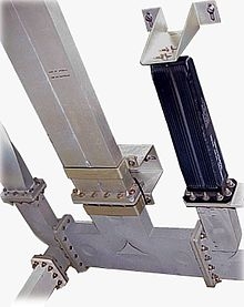
The bottom line, however, is that above a certain frequency coax cannot transmit signals. That’s when a waveguide is used. There are various types of waveguide transmission, but the basic idea is that the signal is inserted at one end of a hollow tube and extracted at the other end. The inner surface of the tube is highly polished so that there is total internal signal reflection. Thus propagation inside the waveguide is often described as a “zigzag” between the walls.

Ordinarily, a signal propagating without a waveguide loses intensity as it expands through three-dimensional space. Its power diminishes conforming to the inverse square law. The frequency of the propagated wave determines the dimensions of the waveguide. Waveguide dimensions diminish as the frequency rises or, saying the same thing, as the wavelength decreases. Generally, the width of a waveguide should be the same order of magnitude as the wavelength of the signal to be conveyed. Accordingly, any given waveguide will have a specific bandwidth in which it is effective.
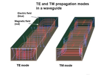
Joints are tightly bolted and gasketed as with pipes intended to hold water pressure. The finished waveguide, if properly designed and matched to the application, will convey high-frequency signals with negligible loss. The propagation of waves through a waveguide is determined from solutions of the wave equations defining the signal. Constraints of the boundary conditions limit the frequencies and forms for the wave function which can propagate in the waveguide. The lowest frequency in which a certain mode can propagate is the cutoff frequency of that mode. The mode with the lowest cutoff frequency is the basic mode of the waveguide, and its cutoff frequency is the waveguide cutoff frequency.

Waveguides may have rectangular or circular cross section depending upon the transmission mode of the wave being guided. Optical fiber has a circular cross-section and small diameter due to the short wavelength of light energy.
Printed circuit boards sometimes contain waveguides, known in the trade as striplines. Even where coax would work, striplines are preferred because they are less expensive and fit on the PCB.
Unlike an electrical circuit that has a hot wire and return conductor (or power and ground rails) a waveguide is a one-way path. Waveguides can take various forms depending upon the frequency. And in theory, all media that convey wave energy by means of confining it to a straight path between the sender and receiver may be considered waveguides. The energy can be low-frequency sound waves, RF signals that are modulated, visible light, microwaves or X-rays. Actually coaxial cable, depending upon the transmission mode, is sometimes considered a waveguide. If you have a TV or a microwave oven, not to mention nerve cells, you have a waveguide in your house.
There are also naturally occurring waveguides. The cry of a whale is only as loud as a jet engine, yet it can be heard thousands of miles away. This is because thermal layers in the ocean form waveguides.
Satellite dishes have waveguides to move the microwave signal from the focal point of the dish to the location of the low-noise block, which contains a down-converter. This makes it feasible to convey the signal 30 ft. or so to the receiver inside the building.
There is no universally accepted definition of microwave radiation. Often it is taken to refer to radiant energy having a wavelength between one meter and one millimeter, or to frequencies ranging from 300 MHz to 300 GHz. (The term “micro” does not refer to a particular wavelength. It just means small.)
Perhaps the most well-known source of microwave radiation is the cavity magnetron, a vacuum tube, that sits in ordinary microwave ovens. As it exists today, it is powered by a high-voltage source. It contains a series of metal cavity resonators. A stream of electrons that interacts with a magnetic field is accelerated past the cavities and radio wave oscillations are excited within them. The high-frequency energy is conveyed via waveguide to the desired location, the interior of the microwave oven.
The first magnetron, invented in the 1920s, had a single resonant cavity. In the 1930’s multiple cavities were introduced, and during World War II the device was used in small radar sets in aircraft.
The reason food heats up in a microwave oven is that radiation emitted by the waveguide rotates polar molecules in the food, and that produces heat. In the popular imagination, food “heats from within” but that is not accurate. Actually the heating effect is greatest at the surface and diminishes with depth, albeit not as rapidly as in convection ovens.
One often sees warning not to take apart microwave ovens because they contain toxic materials and lingering high voltage. Yet there are numerous YouTube videos showing exactly how to do this dissassembly. So here are a few specifics: The hazardous material is actually beryllium mixed in the ceramic that is part of the magnetron tube. Beryllium is a notorious carcinogen when inhaled. So if you are of a mind to disassemble a microwave oven, never cut, grind, or otherwise mess with the ceramic components in the magnetron tube. (Some oven disassembly videos point this out. Some do not.)
When hobbiests disassemble microwave ovens, the components they seem to harvest most often are two ring magnets from the magnetron, the transformer (responsible for most of the oven’s weight), and various switches and announciators from the door interlock and main circuit board. It’s’ possible to find several YouTube videos describing how to repurpose these components. Transformers, for example, can be modified to form the primary component in do-it-yourself spot welders or metal melters.
However, the days of such repurposing may soon be coming to an end. Makers of GaN power transistors claim they can now produce solid-state microwave power amplifiers able to economically replace magnetrons. They have shown example ovens at trade shows with features that are impractical in ordinary ovens, such as beaming one level of microwave energy at, say, mashed potatoes on a plate while beaming a higher level at the meat sitting next to it, so both foods heat correctly.

While the author has tried his best, a good understanding of waveguide technology requires a deeper study. Try Harvey, Microwave Engineering, 1960 approx.
For instance, I would not agree with the statement ” above some high frequency, coaxial lines cannot be used, so we use waveguides”. The truth is that waveguides have much lower loss than coaxial or stripline, the frequency range for a waveguide is determined as the “dominant mode” determined by waveguide dimensions.
Where low loss and low noise figure is needed, waveguides are preferred. During recent technology advances, mm-wave amplifiers and other devices were developed as integrated circuits, so the complete system blocks can be installed in optimum positions, like satellite TV receiver LNBs sitting just at the focus of a parabolic dish. Earlier a waveguide section, often several feet long, was needed to bring a weak signal to receiver input behind a dish.
Jiri,
I apologize for not being more argumentative, but you are absolutely correct in saying that waveguides have lower loss than coaxial.
It is true that coaxial can theoretically be used at any frequency, but only if one is willing to accept a high degree of loss. In coaxial, this eventually becomes astronomical, so the correct statement would be that it is not feasible to use it above a certain frequency. Anything is possible.
Hi Mr .DAVID HERRES
it’s really a nice idea and i understood a lot from your article. can you please suggest on how we can design the wave guide to use the microwave for heating(drying) purpose ? how can we really co relate the waveguide area,shape or… in relation to the area of the dielectric material we can cover while drying?
Very nice, concise well-written article,
Thank you!