Megohmmeter measurements can now be more accurate, rapid and safer than ever before.
JEFF JOWETT, MEGGER
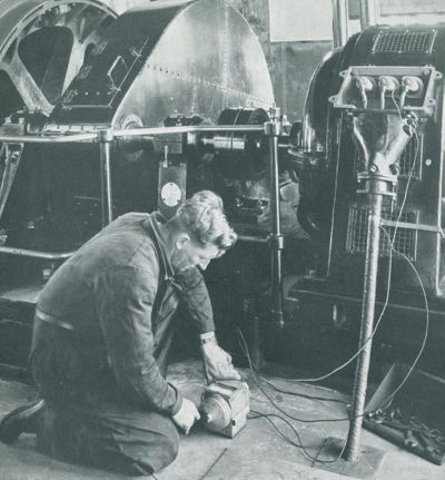
A considerable number of electronics personnel working throughout the electrical industry are military trained. And many of them learned on a simple hand-cranked analog meter, properly termed a megohmmeter, or insulation tester. These testers were typically 500-V units that measured to a few hundred megohms and could run a continuity test to perhaps 100 Ω. Test voltages came from an onboard generator powered by the operator cranking a handle, with a rectifier converting the output to dc. A switch provided the option of a high-resistance insulation test or a low-resistance continuity test. Many of these testers are still operable and, provided they are in good repair and calibrated, there’s no reason they shouldn’t be.
Megohmmeters for decades remained quite similar in design and function. Differences came mainly in the quality of manufacture. But the revolution in microelectronic circuitry created an explosion in rapid upgrading to newer and better designs. Measurements can now be more accurate, rapid and safer than ever before.
First the basics: A megohmmeter measures the quality of electrical insulation by applying a voltage across the insulation and measuring the amount of current that “leaks” through (hence the term leakage current). Voltages are typically applied at a rated operating voltage for routine maintenance or twice-rated and higher for troubleshooting. Currents are minuscule…typically nanoamps…and therefore the tester must have extreme sensitivity. A current of just 5 mA is enough to shock a human. Test voltage and measured current are converted to resistance, in units of millions of ohms (megohms, MΩ). Anything less than a megohm is generally considered unfit for service (exceptions are equipment operating at extremely low voltages and sub-assemblies that will be encased in additional insulation inside of larger equipment).
The original testers did all this, but not much more. Electrical insulation tests determined what needed to be cleaned, repaired, or scrapped and what could remain reliably in service. Insulation testing is a vital link in fire protection, elimination of costly in-service failures, and assurance of safe operation. Simple instruments can perform these functions quite well, and a certain amount of lore has grown up around them over the decades they have been in service.
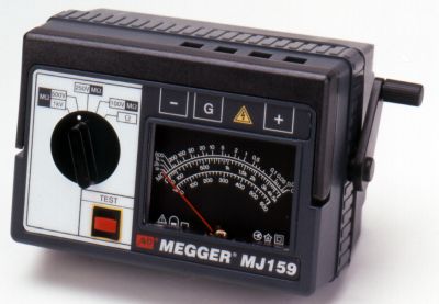
The original testers all had analog movements. They had to; there were no microelectronics. The pointers rested on the high end, pegged low at the start of the test due to capacitive charging currents, then drifted steadily (it was hoped) back to the high end or stopped on a measurement. Many operators became adept at watching the travel and paid less attention to actual numbers.
This skill was hard to teach; it had to be learned and is still practiced by veteran technicians. But analog movements were sensitive and withstood little banging about. They also could suffer from parallax and the operator’s interpretation as to just where the pointer stopped.

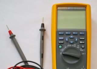
LCDs introduced digital measurements. These units generally could be dropped and put right back into service, provided they didn’t land directly on the display; a huge bonus in savings of time and cost. Digital measurement also could be extremely precise, down to a percent or two in quality instruments, and required no interpretation. But the pointer travel cherished by the veteran techs was lost.
Then technology came to the rescue once more! Combination displays are available in quality instruments, with an electronic pointer and digital result when it rests. Remember: Look for a logarithmic arc that is expanded for better resolution on the all-important low end of the scale. A mere curved bar graph doesn’t behave like a genuine analog.
Analog technicians got accustomed to good insulation measuring off the high end of the scale, marked with an infinity symbol. This is always desirable, but not always understood.
Infinity is not a measurement; it simply means the insulation is better than that particular tester can measure within its stated parameters. Old original testers might have gone to only 200 MΩ, or more likely 1,000 MΩ (1 Gigaohm). This was enough to weed out bad or faulty equipment. But it didn’t provide much more information.
Quality testers now measure into the Gigaohm or Teraohm (1,000 GΩ) ranges. There are two prime advantages to this expanded range. Insulation resistance drifts slowly and relentlessly down during operation and can act like a car odometer in reverse; the lower the number, the less remaining life.
This behavior can be trended to provide a timeline for maintenance and replacement. Higher numbers enable early warning if resistance is falling rapidly, as from moisture ingress or nearby sources of contamination. Second, manufacturers of insulating materials constantly develop larger cross-linked macromolecules that boost quality and raise early measurement values. The measurement capabilities of testers have had to keep up with such developments.
Finally, you must record the result if your test does go to infinity (over-range) and know how high your tester can measure. Range limit typically rises with test voltage, so be aware of the voltage used and the limit of that range. Then record it as greater than
that limit (>100 GΩ, for instance). Nothing is a “fail”
at range limits.
HAND-CRANK VS BATTERY
Line power was not amenable to many of the environments in which testing took place, such as construction sites and remote circuits, so the hand-cranks developed a considerable mystique over the years. When batteries came into use, they reinforced, rather than superseded, the hand-crank mystique. Early battery operation was spotty and earned a bad reputation, even to the extent of banishment in some quarters. Batteries could die before the end of a shift, leaving a technician without a tool. Worse, as they lost charge, readings could become regressively less accurate.
By the late 1970s, battery technology had improved enormously, and these problems could be circumvented. A quality insulation tester now can run 2,000 tests with a single set. Furthermore, full specified capabilities are available right up until the LO BAT warning appears. Nonetheless, hand-cranks have become so entrenched that they continue to enjoy wide use. Veteran operators may insist they can tell something about the quality of a test item by the turn of the generator. But, like the handling feel of a car, this claim is scientifically unquantifiable.
Insulation testers provide a lot of voltage but have little power. Initially, this may seem counterintuitive, but a little reflection makes it clear. An item under test that passes more than a few milliamps is no longer fit as insulation. Hence, megohmmeters are commonly limited in output to about 5 mA or less. That low level makes the tester essentially safe, but not the test item. Highly capacitive test items (long runs of cable, large windings in motors and transformers) could store enough energy to be lethal. When the test ends and the voltage gradient provided by the megohmmeter ceases, all this stored energy will discharge.
In the past, protection against such difficulties was largely left to good working practices. Some testers had discharge switches, but they could be accidentally overlooked. A rule of thumb was to discharge five times the length of the test; i.e., a ten-minute test was left grounded for fifty minutes before disconnecting, presuming that would be more than enough.
The order of the day now is redundant safety. Safe working practice is augmented by a discharge circuit in the instrument, complete with audible and visual warnings. The operator need only watch while the progress of the discharge is shown on the display. Protective circuitry is also in place at the beginning and during a test. If a circuit is energized or becomes energized during the test, modern testers warn the operator and disable testing.
In bygone days, insulation testers were routinely returned for “warranty” repair with burn tracks across the board. Live hookup; operator error; no warranty.
Now, a quality tester senses live voltage and disable testing. It doesn’t stop there. Continuity testing — the corollary to insulation testing, to assure that circuits are properly connected — requires a low-impedance test circuit. But the high resistance discharge circuit remains engaged until the tester senses that both leads are connected across a safe, low-resistance circuit.
Old testers once came with a stack of test record cards. The technician would write in the data and sometimes connect the dots to develop a graph. These were often hung on machinery in waterproof jackets. The practice was time-consuming and prone to human error. Modern testers store data with the push of a button; even all the data of a prolonged procedure. Aside from easy storage, this practice also eliminates a lot of dispute with third parties and authorities. Test reports and certificates are printed just as easily. And mathematical calculations, such as temperature correction, take place automatically and without error.
TEST VOLTAGE
Insulation tests once took place at a single voltage to which were added a few critical selector choices. But only one read directly. Other measurements had to be corrected by a multiplier or division, which was printed on the selector. Variacs provided infinite voltage adjustment, but only one or two positions read directly. All others had to be corrected by a factor on the scale plate. Eventually, there were multiple selector positions that could all be read directly. They were an enormous help and dominated for about half a century. Now, advanced testers afford direct reading in 1-V increments across the entire range of the tester.
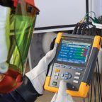
Additionally, testers can measure multiple parameters besides insulation resistance, directly displaying leakage current (the inverse of resistance), frequency, actual test voltage, capacitance, and other parameters. Pass/fail audible indicators can be set up and multiple measurements displayed simultaneously. Standard procedures can run automatically while the operator attends to another task.
International standards provide operating procedures and results analysis. Two of the most important are IEC 61010, which specifies general safety requirements for several types of electrical equipment, and IP (ingress protection) rating. The IEC CAT, or category, rating indicates the level of safety against arc flash/arc blast. Always know the CAT rating of an instrument and apply it accordingly.
Ingress of foreign materials…dust, moisture…won’t be lethal to the operator but can be to the instrument. Enclosures have vastly improved over the old Bakelite and phenolic materials. The IP rating quantifies enclosure performance, indicating objectively and reliably under what environmental conditions the instrument will remain in service. There is even a rating for immersion, although insulation testing generally doesn’t take place underwater.
All in all, the evolution of instrumentation over a century has greatly reduced the possibility for error. But there are still some best practices to keep in mind when running insulation tests: Testing should follow Safe Working Practices of the employer, union, or standards source. Isolate the test item and keep it inaccessible to onlookers or passersby. Run a performance test on the test equipment and include the leads. Damaged leads are often an overlooked source of confusing or inaccurate results.
Know the basic electrical configuration of the test item; you will test whatever insulation is between the leads. Motors and transformers will have open windings so you’re not running a continuity test. Cap open ends or separate them to eliminate the possibility of arcing. Know the unit of measurement to prevent confusing MΩ with GΩ or TΩ. A good tester will show units on the display, but operators sometimes overlook it.
Above all, be sure to account for time and temperature. Both profoundly affect readings. Adjust to a common temperature using the coefficient for the insulating material (part of the specs). Take readings at the same test time, once digits settle (e.g., 30 sec, 1 min).
Finally, single-conductor cable cannot be tested conventionally because there is no place to attach the second lead. Special accommodations can be made to test single conductors, but don’t expect the standard procedures for multi-core to apply.


It was interesting when you explained that megohmmeters apply voltage to insulation and measure how much of it leaks through. My brother needs to buy some electrical testing equipment to use for the local service business he plans on starting this May. I’ll pass your article along to him so he can determine if he’ll need a megohmmeter for his work!
Interesting blog, good information is provided regarding better instrumentation for insulation testing. It was very useful, thanks for sharing the blog.