Like a logic analyzer, a bus analyzer is capable of monitoring and capturing bus communication data. Both instruments decode, analyze and display that information. There are, however, significant differences. While a logic analyzer can display data from any of a large number of buses, an individual bus analyzer is built to work with only a […]
Featured
Logic analyzer basics: The difference between a scope and a logic analyzer
The logic analyzer is an advanced instrument that displays the content of numerous digital data streams simultaneously and in various formats. It is continuously evolving. Manufacturers are offering new and ever more advanced features that facilitate with great precision design, debugging and repair of digital systems. While the oscilloscope remains relevant in the digital domain, […]
Basics of testing CMOS

The term complementary metal-oxide semiconductor (CMOS) has become a partial misnomer because the dielectric layer that separates gate and source is now rarely a metal oxide. The name persists despite this change. CMOS refers to pairs of MOSFETs in symmetrical configurations, which in turn are slightly modified FETs. CMOS circuits have become by far the […]
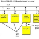
Testing and debugging the I2C digital data bus

“Bus” is an old term derived from conductive elements that are part of an electrical distribution system, generally referring to short specialized conductors separate from the overhead or underground cable. Typically, the old-style buses consist of bare copper bars, often having a rectangular cross-section, firmly mounted in an enclosure and capable of carrying current at […]
Measuring clock and oscillator frequency
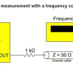
A clock may refer to an oscillator that has been designed to provide a timing signal to facilitate operation of one or more synchronous processors. In contrast, asynchronous operation does not require a clock because each step initiates upon completion of a prior step. It is potentially faster than synchronous operation because there is not […]
Characterizing digital logic signals with an oscilloscope

Transistor-transistor logic (TTL) and complementary metal oxide semiconductor (CMOS) logic are the principal types of integrated circuit-based logic gates implemented in digital circuitry. TTL employs bipolar junction transistor technology while CMOS uses the field-effect transistor concept at the input. TTL consumes far more power than CMOS, which is one reason CMOS has eclipsed TTL as […]
Basics of measurement resolution
In electronic instrumentation, resolution is a measure of the distance in amplitude at which we can distinguish between two points on a waveform. This is not the same as accuracy, which is a measure of how closely a waveform as displayed or measured agrees with the signal at the instrument’s input. One of the principal […]
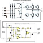
Making measurements on balanced transmission lines

Stray electrical fields are everywhere. They infiltrate signal transmitting and receiving devices as well as the transmission lines that connect them, taking the form of noise and unwanted signals. The effect is to raise the signal to noise ratio, obscuring desired analog and digital information. There are mitigation techniques, but to be effective they must […]
Basics of operating oscilloscope arbitrary waveform generators
An arbitrary function generator (AFG) produces oscillating energy that takes the form of periodic or one-shot waves. We should begin by asking: What is the difference between an AFG and an arbitrary waveform generator (AWG)? Also, what is meant in these contexts by “arbitrary?” Arbitrary as applied to waveform generation means that the user can […]
Avoiding electrical hazards in the lab and repair shop
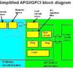
There are three principle hazards in working with electrical equipment. Any of these can be lethal and cause injury or property loss. They are electrical shock, arc flash, and electrical fires. Electrical shock strikes without warning. It is immediate and instantaneous, but its effects may persist for years. Sometimes an individual exposed to electrical shock […]
