Engineers running hardware-in-the-loop simulations face difficulties associated with how to devise sensor signals that truly exercise advanced drive assistance systems.
DAVID A. HALL, National Instruments Corp.
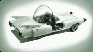
More than 50 years ago, in 1959, the Cadillac Cyclone XP-74 concept car featured two modified aircraft radars designed to alert the driver about oncoming traffic. Today, an automotive radar sensor is smaller than a hockey puck and has transitioned from concept to reality.
Primitive techniques for collision and lane change avoidance are being replaced with advanced drive assistance systems (ADAS). These new systems introduce new design and test challenges. Modern ADAS architectures combine complex sensing, processing, and algorithmic technologies into the what will ultimately become the guts of autonomous vehicles. For consumers, the growth in ADAS technology provides comfort and convenience. For engineers, the evolution of ADAS provides a combination of job security mixed with quite different design and test challenges.
As ADASs evolve from simple collision-avoidance systems to fully autonomous vehicles, they demand sensing and computing technologies that are complex. For example, consider the sensing technology on the Tesla Model S, which combines information from eight cameras and 12 ultrasonic sensors as part of its autopilot technology. Many experts are claiming that the 2018 Audi A8 is the first car to hit Level 3 autonomous operation. At speeds up to 37 mph, the A8 will start,
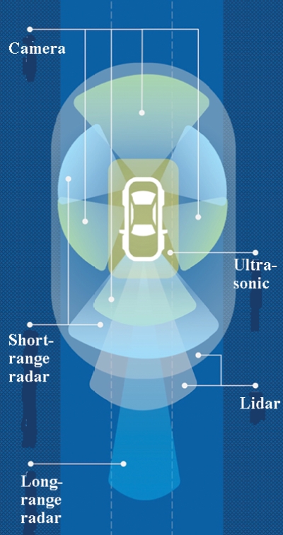
accelerate, steer and brake on roads with a central barrier without help from the driver. The car contains 12 ultrasonic sensors on the front, sides, and rear, four 360° cameras on the front, rear and side mirrors, a long-range radar and laser scanner at the front, a front camera at the top of the windscreen and a mid-range radar at each corner.
As a result, autonomous vehicles employ significantly more complex processing technologies and generate more data than ever before. As an example, the Tesla Model S contains 62 microprocessors – more the three times the number of moving parts in the vehicle. In addition, Intel recently estimated that tomorrow’s autonomous vehicles will produce four terabytes of data every second. Making sense of all this data is a significant challenge – and engineers have experimented with everything from simple PID loops to deep neural networks to improve autonomous navigation.
SYSTEM-LEVEL TEST
Increasingly complex ADAS technology makes a lot of demands on test regimes. In particular, hardware-in-the-loop test methods, long used in developing engine and vehicle dynamics controllers, are being adapted to ADAS setups.
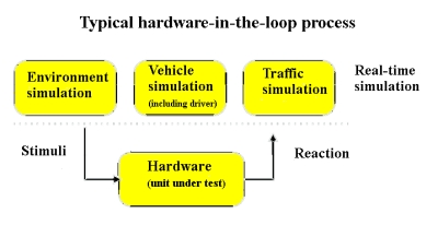
 HIL test systems use mathematical representations of dynamic systems which react with the embedded systems being tested. An HIL simulation may emulate the electrical behavior of sensors and actuators and send these signals to the vehicle electronic control module (ECM). Likewise, an ADAS HIL simulation may use real sensors to stimulate an emulation of the ECM and generate actuator control signals.
For example, a HIL simulation platform for the development of automotive anti-lock braking systems may have mathematical representations for subsystems that include the vehicle dynamics such as suspension, wheels, tires, roll, pitch and yaw; the dynamics of the brake system’s hydraulic components; and road qualities.
A point to note is that the in-the-loop notation means the reaction of the unit being tested influences the simulation. HIL methods verify and validate the software in the physical target ECUs. So HIL test benches must provide the ECU with realistic real-time stimuli and simulated loads. Multiple ECUs get tested in network HIL setups that wring out the bus systems, sensors, and actuators.
More recently, vehicle-in-the-loop methods use a physical car to replace vehicle simulations and most of the virtual ECUs. This approach comes in handy for testing safety critical ADAS functions by, say, crashing into virtual obstacles while operating the real vehicle.
The way an ADAS typically works is that it first processes the raw sensor data via feature and object recognition algorithms. The result is a data set that resembles a grid-based map of the environment or a list of recognized objects (such as trees, pedestrians, vehicles, and so forth). A situation analysis algorithm combines this processed data and estimates the current traffic situation. This situational analysis gets forwarded to the ADAS application. The application finally decides on actions to take such as slowing down or triggering an emergency brake.
Many HIL tests of ADAS functions boil down to sending simulated object lists to the UUT (unit under test). Depending on the sensor systems involved, the object lists may include information about object kinematics as well as whether the object is a pedestrian, vehicle, or something else.
Besides actual sensor data, the ADAS application needs supplementary vehicle data from other ECUs. This information usually passes to the UUT via the CAN bus and generally includes details like gear rate, acceleration, engine speed, steering angle, or GPS data. All ADAS require at least some of this information to check the plausibility of the situation analysis. The ADAS makes safety-critical interventions only if all this information is consistent.
When testing ADAS functions within HIL regimes, there can be a variety of UUTs and interfaces. For example, a single ECU might be tested while it runs core emergency functions such as a radar-based emergency brake-assist. Or a dedicated ADAS ECU might receive sensor information from other control units. Depending on the setup, multiple real ECUs may be part of the test bench and connected via automotive network systems like CAN, FlexRay, or Automotive Ethernet.
In an HIL test bench there can be several points at which virtual data is added. One option is feeding simulated data to physical sensors. Of course, real ADAS have multiple sensors so this strategy entails simultaneous generation of multiple signals. In the case of cameras, for example, engineers might show each camera a sequence of images of actual scenery via a screen or projector. For radar returns, the HIL system needn’t generate the radar output, just simulated echoes coming back.
One advantage of using physical sensors in HIL testing is that there’s no need to modify the UUT for testing purposes – the simulated signals come via the same physical interfaces as found in real vehicles. Among the biggest challenges is assuring the quality of the injected signals. For example, images projected on a screen might not represent the dynamic range a camera would see in real life. The classic example is that of a car driving straight into a blazing sunset, then descending a hill and plunged into dusk. All in all, the injection of data into a physical sensor involves few modifications of the UUT, but the accurate representation of scenarios can be quite demanding and not currently possible for all sensors.
Consequently, engineers sometimes inject virtual data after digitization as, say, injecting data after the ADC stage of a radar, or by providing electrical stimulation of a camera’s imager. This approach is quite product-specific – there is no such thing as a standard radar or camera hardware/software interface, so establishing the connection may take some work. Additionally, the fact that data may no longer come from the physical sensor can force some software and hardware modifications of the UUT.
PLATFORM-BASED APPROACH TO HIL
Manufacturers such as National Instruments offer a platform-based approach to HIL testing. Key features of NI’s HIL test approach include a tight synchronization among numerous PXI instruments to enable simulations of driving scenarios and sensors. Particularly important in ADAS and autonomous driving applications is NI’s FPGA technology. FPGA technology enables engineers to design HIL test systems with extremely fast loop rates for quick decision making.
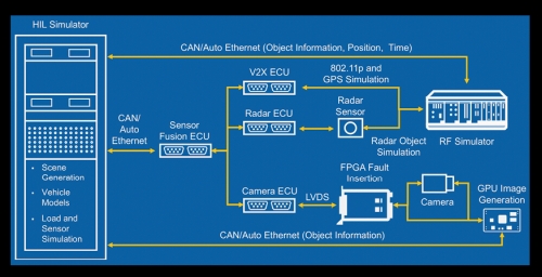
One recent example of an HIL test system using the platform-based approach to sensor fusion testing was demonstrated by a consortium called ADAS Innovations in Test. This group is a collaboration between NI alliance partners S.E.T., Konrad Technologies, measX, and S.E.A. At the recent NIWeek conference, the group demonstrated an ADAS test setup which can synchronously simulate radar, lidar, communications, and camera signals for an ADAS sensor. In one case, the setup was able to simulate a virtual test drive using IPG CarMaker and NI VeriStand software.
Modular systems such as PXI simulate many vehicular physical signals – effectively recreating the physical environment of the ADAS sensor or ECU. Synchronization is a critical requirement of the PXI modules – because all these signals must be precisely simulated in parallel. The ECU needs the radar, V2X and camera signal to arrive simultaneously if it is to process and understand the scenario and act accordingly.
HIL test techniques based on a platform let engineers simulate a virtually unlimited duration of “driving time.” The lengthy test time provides more opportunities for finding problems and lets engineers better understand how the embedded software performs in a wide range of situations.
As a result of simulating driving conditions in the lab, engineers can identify critical design flaws much earlier in the design process.
For example, at Audi AG, the radar team recently adopted a PXI-based system radar simulation. Project lead Niels Koch says radar hardware-in-the-loop simulation enabled them to “simulate ten years of sensor environments within few weeks.”
Fifty years ago, a front-mounted radar system that notified the driver of oncoming traffic was a gimmick. Five years from now, it will be the difference between life and death for passengers in autonomous vehicles. Given the impending safety and regulatory considerations of this technology – engineers will utilize HIL test techniques to literally simulate billions of miles of driving.
Advanced systems like autonomous vehicles are quickly rewriting the rules for how test and measurement equipment vendors must design instrumentation. In the past, test software was merely a mechanism to communicate a measurement result or measure a voltage. Going forward, test software is the technology that allows engineers to construct increasingly complex measurement systems capable of characterizing everything from the simplest RF component to comprehensive autonomous vehicle simulation. As a result, software remains a key investment area for test equipment vendors – and the ability to differentiate products with software will ultimately define the winners and losers in the industry.

Thanks for posting a detailed guide on this. This is really helpful.