In this age of misinformation, you can add coaxial cable to the list of items for which it is easy to get steered wrong based on internet searches. Much of the bogus online commentary about coax relates to cable loss, cable impedance, and standing waves. Here are a few basics that may help sort the truth from cable mythology.
One misconception concerns cable impedance and cable loss. The characteristic impedance (Z0) of a transmission line is the ratio of the amplitudes of voltage and current of a single wave propagating along the line. Another way of stating it is that it is the ratio of voltage and current of a wave traveling in one direction in the absence of reflections in the other direction. Additionally, characteristic impedance is by definition the input impedance of a transmission line in the ideal case where the transmission line is infinitely long.
All uniform transmission lines possess a characteristic impedance. For coaxial cable, there are two principle standards. Fifty-ohm coax is used in professional and commercial installations, while seventy-five ohm coax is found mostly in domestic TV and higher-frequency FM installations. Demanding computer applications require higher values. Other available characteristic impedances include 25, 95 and 125 ohms.
Physical specifications that determine characteristic impedance are spacing between conductors, which is determined by the thickness of the dielectric layer, the dielectric index and the thickness of the conductors, which determines their resistance. You can find online coaxial cable impedance calculators that accept inputs of outer diameter dielectric width, inner conductor diameter width and either the dielectric constant or velocity of propagation (VoP, the speed at which RF propagates through the cable conductors) values to calculate the intrinsic impedance of the coax.
That said, there is some confusion about cable intrinsic impedance and loss. Different coax cables with the same intrinsic impedance can exhibit different signal loss qualities. Consider RG-59/U coax, often used for low-power video and RF signal connections. The cable has a characteristic impedance of 75 Ω and a capacitance of around 20 pF/ft (60 pF/m). The suffix /U means for general utility use. RG-59 is often used at baseband video frequencies, such as composite video. But its high-frequency losses are too high to allow its use over long distances. In these applications, RG-6 or RG-11 is used instead. Both RG-59 and RG-6 coax have an intrinsic impedance of 75 Ω though their loss qualities are quite different.
One video blogger even made a YouTube video about replacing RG-59U with RG-6 in an ordinary home tv installation. In a nutshell, he recorded a signal about 15% higher by replacing RG-59 with Rg-6. In a residence he was servicing, the TV reception went from 14 channels to 33 channels with the better coax.
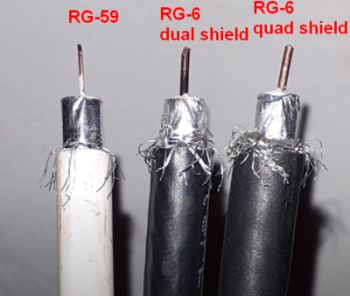
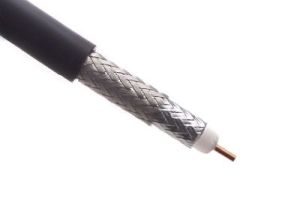
 The reason for the different performance becomes clear by examining the cable construction. A conventional RG-59 coaxial cable has a 20 AWG copper center conductor. Some brands use copper-clad steel for their center conductor material. Standard RG6 coaxial cable has a larger 18 AWG copper center conductor, contributing to its lower losses. There can be differences in the shielding as well. RG-59 cables typically have less shielding than RG-6 versions. Standard RG-6 coax has two shield layers compared to one for RG-59. Low-loss versions of RG-6 have four shield layers and are dubbed quad-shield. For super-long cable runs, there are special low-loss cables. One such type is the LMR 600, though it is 50 Ω and designed mainly for feeder runs and wireless communication infrastructure.

Coax applications are:
CMP – Plenum, suitable for use in ducts, plenums and other space used for environmental air.
CMR – Riser, suitable for use for vertical runs in a shaft.
CMG – General, suitable for communications if not in a riser or plenum.
CMX – Suitable for use in dwellings if not in a riser of plenum.
These classifications relate to the combustibility of the outer layer and its potential for hazardous smoke propagation.
There are other applicable cable-type NEC articles, including article 725, Class1, Class 2 and Class 3 remote-Control, Signaling and Power-Limited circuits.
A signal conveyed in a transmission line is wholly or partly reflected back toward the source when it encounters a discontinuity in the characteristic impedance in the line, or if the line is not terminated in its characteristic impedance. This can be due to incorrect choice of terminating or slicing hardware, mismatch at the receiver or physical damage to the line that occurs after installation.
That leads to another misconception about coaxial cables: radiation. Some commentaries suggest that a mismatch at the end of the cable may cause the coaxial cable itself to radiate part of the signal. In reality, the only condition that can cause a coaxial cable to radiate is when the current flowing in the center cable is different than the current flowing in the shield. In other words, the sum of the center conductor and the shield currents don’t sum to zero resulting in what’s called a common mode current. Note that this can happen even when the impedances at each end of the cable match the cable impedance.
The classic example of where an imbalanced current can flow in a coaxial cable is when a transmitting antenna is attached to one end and the element attached to the cable center conductor radiates more than the element attached to the cable shield. There can be other situations where imbalanced currents can arise, but they typically don’t happen when cables connect ordinary electronic equipment.
Finally, we mention a misconception that concerns standing waves. Standing waves are the consequence of signal reflections. If a step voltage is applied to the end of a cable having a characteristic impedance matching that of the source, the step will propagate down the line. Suppose the signal encounters an open circuit at the end of the cable, the current will abruptly go to zero. Because charge continues to arrive at the end of the line, while no current leaves the line because it is open, conservation of charge requires that there be an equal and opposed current going into the end of the line. This equal and opposite current is the reflected current. There is a reflected voltage that behaves in a similar manner.
As a reflected wave travels back up the cable, it adds to the incident wave where the two are in-phase and subtracts from the incident wave where the two are out of phase, forming a standing wave. Where the points of minimal energy and maximum energy appear in the cable depend on the frequency.
The standing wave idea has fostered a misconception still found on some corners of the internet. The misconception is that the coaxial cable should have a length corresponding to a half-wavelength at the frequency of the signal it carries. Internet sites catering to CB radio sometimes still contain statements of this sort. The rationale for this claim is that the half-wavelength point corresponds to a voltage minimum for the frequency in question. One interesting point about such advice is that it often neglects the VoP of coaxial cable when suggesting a cable length, instead basing advice on RF wavelength in free-space. Thus a cable length equaling that of a half-wavelength in free space won’t yield a voltage minimum at its end for the frequency in question.
In any event, the standing wave ratio measured in coaxial cable depends on the point of measurement. It really has no bearing on the energy delivered to the load. The way to minimize reflections in coax is simply to make sure the source and load impedances equal that of the cable.


Leave a Reply
You must be logged in to post a comment.