The new Tektronix AFG 31000 Arbitrary Function Generator is noteworthy in that the Home screen, accessed by pressing the Home button on the front panel, permits the user to choose a Basic or Advanced mode. The Basic mode resembles a traditional AFG, with a library of internal waveforms and menus that permit the user to adjust parameters such as frequency and duty cycle. The Advanced mode makes available enhanced features that facilitate the many tasks that today’s electronics engineers tackle in laboratory, shop or in the field.
The large touch screen has prominent tabs choosing basic or advanced, in addition to smaller tabs that bring up ArbBuilder, Utility and Help. Users will be eager to try out the new ArbBuilder with enhanced features, but we’ll start with some fundamental functions.
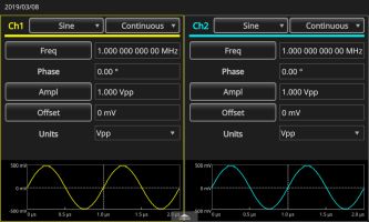
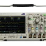
Pressing Basic, in a two-channel model, we see in the split-screen format a drop-down menu containing the internal library of waveforms permanently stored in the instrument memory. A second drop-down menu specifies whether the selected waveform is to be displayed in continuous, modulated, swept or burst mode. To see the functions displayed with modifications, in the AFG front panel channel section, insert two BNC cable connectors into the Channel One and Channel Two output ports and run them to a digital storage oscilloscope such as the Tektronix MDO3000, connecting two analog channel input ports.
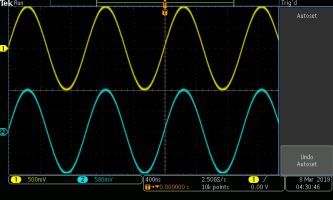
Accessing the two internal waveforms shown in the two AFG drop-down menus, the user can select twelve alternative functions plus Arbitrary. The same or different waveforms can be selected independently and sent to the oscilloscope. There, they are redigitized and can be stored, analyzed, modified or emailed.
For example, turn on both channels in both instruments. With ramp in Channel One and square wave in Channel Two displayed, press the Math button on the oscilloscope front panel. The horizontal Math menu appears with default Dual Waveform active in the horizontal Math menu. Pressing the associated soft key, we see that sources are Channel One and Channel Two and that the operator is set at Add. The sum of the two waveforms is shown in red, the dedicated Math color.
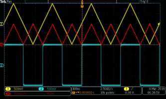
Now turn off Channel Two in both instruments and turn off Math in the oscilloscope. Notice in the AFG Channel Two basic display that the square wave still appears, and the various waveforms can be selected and modified. That is because the on-off button is applicable only to the channel output.
In the AFG, turn the Channel One waveform back to Sine. The oscilloscope display responds instantly. Now we’ll see how waveform metrics correspond in the two instruments.
In the AFG, the middle part of the Basic mode screen shows waveform parameters. They are Frequency, Phase, Amplitude, Offset and Units. If you touch Frequency, the displayed value shifts to the reciprocal, Period. The Frequency/Period of the signal at the AFG output does not change for now. Similarly, touching Amplitude, Offset and Units changes the way the waveforms are measured, but not the actual signals.
Signal parameter can, however, be changed using buttons in the Basic Mode front panel controls in conjunction with the front panel or on-screen number pad, whichever is more convenient for you. For example, to change the frequency of the sine wave to 2 MHz, press the Frequency/Period button in the front panel Basic Mode section. In the number pad or using the touch screen, enter 2. The frequency changes to 2.000 MHz. Similarly, Amplitude can be changed.
Pressing Default in the Setup Section, the frequency reverts to 1 MHz and the amplitude is 1.0-V peak-to-peak.
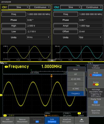
In the oscilloscope Wave Inspector section on the front panel, press Measure. In the horizontal Measure menu, press the soft key associated with DVM and use Multipurpose Knob a to scroll down to Frequency. As expected, the frequency measures a stable 1.0000 MHz, exactly the same as the AFG, but carried to fewer decimal places. Don’t expect the amplitudes to correspond at this frequency. There is too much loss in the BNC cables and the oscilloscope DVM reports Over Bandwidth.
The Tektronix AFG 31000 series offers four modes for viewing the internal waveforms. They are Continuous, Modulation, Sweep and Burst. All waveforms do not work in all modes. Here is a summary:
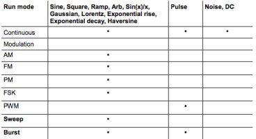
Modulation can consist of amplitude modulation (AM), frequency modulation (FM), phase modulation (PM) and frequency shift keying modulation (FSK). Besides modulation, signals may be swept or in bursts. The swept signal varies linearly or logarithmically. Settings include Start Frequency, Stop Frequency, Amplitude, Offset, Units, Sweep Time, Return Time, Center Frequency, Frequency Span and Hold Time.
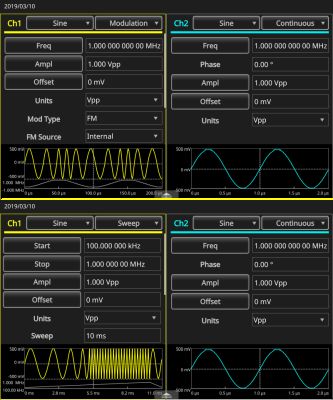
In Basic Mode the AFG can also output a Burst Signal. The instrument provides these trigger sources to enable the burst mode: internal or external trigger signal, manual trigger and remote command.
A screen image can be saved to a USB flash drive. Follow these steps:
(1) Insert a USB flash drive into the front panel USB slot.
(2) Set the display to show the screen you want to save.
(3) Simultaneously press the two arrow keys underneath the navigation control on the front panel.
(4) A message appears on the screen indicating the image was saved.
The AFG 31000 in Advanced Mode can perform a great many complex operations with a relatively intuitive and user-friendly interface. The focus in this AFG Advanced Mode is that it enables users to generate long waveforms and those with complex timing. While it is true that the AFG Basic Mode — and for that matter, even the internal AFG in the Tektronix MDO3000 — both have arbitrary waveform generation capability, the AFG 31000 in Advanced Mode introduces enhanced features. Users can control how the waveforms in Sequencer are organized, including repeat, wait, jump, go to or triggering with events in external trigger, manual trigger, timer and SCPI commands.
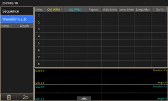
In Advanced Mode, every point in an arbitrary waveform is output once each cycle at the pace of the specified sampling rate, free of skips or repetition. Advanced Mode is appropriate when jitter and phase noise cannot be tolerated, as in serial bus simulation, or when narrow anomalies are to be simulated in long waveforms, for example to test prototypes for such vulnerabilities. In this situation, the waveform details are retained, jitter and phase noise are reduced, and in each cycle the number of samples is consistent.
Advanced Mode has four output modes: Sequence, Continuous, Triggered and Gated. Sequence offers enhanced flexibility when generating waveforms characterized by complex timing. In the Continuous output mode, the AFG 31000 outputs an ongoing one-step waveform sequence. In Triggered, one cycle of a waveform is output when the AFG receives a trigger input. After one cycle, the instrument returns to its initial state until another trigger input is received. In Gated mode, the AFG outputs a one-step waveform sequence when it receives a valid gate signal, then stops upon receipt of another gate signal.
The Advanced Mode outputs the waveform in accordance with the sequence table, including loop and conditional jump. The waveform is output as defined by the sequence that is selected. A variety of waveforms can be output in any specified order.
The Advanced output screen permits the user to choose from available waveforms, open a saved waveform by selecting Sequence and create and save a new waveform.

Leave a Reply
You must be logged in to post a comment.