DAQs work within computer systems. However, in order to make data acquisition work you must transmit and receive signals in order to process the information. There are a wide variety of interfaces used to connect data acquisition hardware to computers such as PCI bus, Ethernet and USB protocols. In addition to interfaces connecting DAQ systems to standard PCs, there is growth for embedded systems markets where programs are written and deployed on the DAQ system itself, allowing it to run standalone.
Regardless of the hardware used, you must transmit information to the hardware and receive information from the hardware. You send configuration information to the hardware such as the sampling rate, and receive information from the hardware such as data, status messages, and error messages. You might also need to supply the hardware with information so that you can integrate it with other hardware and with computer resources. This information exchange is accomplished with software.
There are two kinds of software: Driver software and application software.
In the early 1980’s, most analog input and output devices offered 12-bit resolution. There were also some lower speed products with greater than 12-bit resolution and a number of high speed products offering resolution in the 8 to 10-bit range. Today, the technology has changed and the standard resolution is 16-bit, with DAQ products offering resolutions up to 24-bit while some of the higher speed, lower resolution products are even challenging the performance of low end digital oscilloscopes.
In a standard data acquisition configuration, one or more I/O interface is connected directly to a PC. The PC, then directly controls the I/O, storing all data either in memory or on a disk drive.
For DAQ devices, there is associated driver software that you must use. Driver software allows you to access and control the capabilities of your hardware. Among other things, basic driver software allows you to:
•Bring data on to and get data off of the board
•Control the rate at which data is acquired
•Integrate the data acquisition hardware with computer resources such as
processor interrupts, DMA, and memory
•Integrate the data acquisition hardware with signal conditioning hardware
•Access multiple subsystems on a given data acquisition board
•Access multiple data acquisition boards
Application Software
Application software provides a convenient front end to the driver software.
Basic application software allows you to
•Report relevant information such as the number of samples acquired
•Generate events
•Manage the data stored in computer memory
•Condition a signal
•Plot acquired data
Many data acquisition hardware devices contain one or more subsystems that convert (digitize) real-world sensor signals into numbers your computer can read. These devices are called analog input subsystems (AI subsystems, A/D converters, or ADCs). After the real-world signal is digitized, you can analyze it, store it in system memory, or store it to a disk file.
Analog signals are continuous in time and in amplitude (within predefined limits). Sampling takes a “snapshot” of the signal at discrete times, while quantization divides the voltage (or current) value into discrete amplitudes.
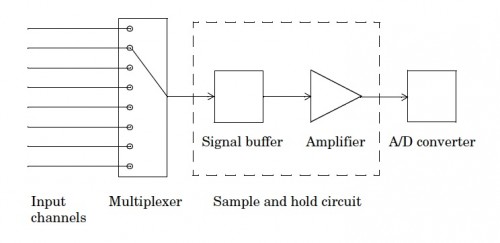
For most applications, the time interval between samples is kept constant (for example, sample every millisecond) unless externally clocked. For most digital converters, sampling is performed by a sample and hold (S/H) electronic switch connected to a capacitor. The operation of an S/H circuit follows these steps:
1 At a given sampling instant, the switch connects the buffer and capacitor to an input.
2 The capacitor is charged to the input voltage.
3 The charge is held until the A/D converter digitizes the signal.
4 For multiple channels connected (multiplexed) to one A/D converter, the previous steps are repeated for each input channel.
5 The entire process is repeated for the next sampling instant.
Hardware can be divided into two main categories based on how signals are sampled: scanning hardware, which samples input signals sequentially, and simultaneous sample and hold (SS/H) hardware, which samples all signals at the same time.
Special thanks to National Instruments, Engineer’s Edge, and MathWorks.

Leave a Reply
You must be logged in to post a comment.