Harmonics are waveforms that may accompany a periodic fundamental (also known as the first harmonic) in a divergent infinite series. When they arise, their frequencies are integer multiples of the fundamental. If this fundamental is 60 Hz, the second harmonic is 120 Hz, the third harmonic is 180 Hz, the fourth harmonic is 240 Hz and the fifth harmonic is 300 Hz.
Most utility power, 50 or 60 Hz, is produced and distributed as electrical energy whose voltage conforms to a sine wave. The sine wave arises because of the rotary nature of the generator. Minor imperfections in windings and air gaps can add distortion, but at the utility level this is minimal, and in sensitive electronic applications the end-user can eliminate it by using resonant filters to suppress the unwanted frequencies.
What is unique about a sine wave is that it includes no harmonics, just the fundamental sine wave frequency. But that is a matter of semantics. When we speak of harmonics, we are generally referring to signals that are in addition to and higher in frequency than the fundamental. In that sense, there are no harmonics that accompany a pure sine wave. All the power is at the single fundamental frequency of the sine wave.
Seen in an oscilloscope’s time domain display, it is difficult to know for sure that a given waveform is an absolutely pure sine wave. It has a characteristic shape, crossing the X-axis vertically (if it has a zero dc component) and gradually transitioning to a horizontal segment as the positive and negative going signal peaks out. That is because in a sine function the rate-of-change is inversely related to the amplitude, negative or positive.
The divergence from a pure sine wave may be subtle. But in the frequency domain display, amplitudes at frequencies other than the fundamental are easy to see if they rise above the instrument’s noise floor. The frequency domain can be invoked by pressing FFT in the Math menu of a mixed-domain oscilloscope. Another way to go is to connect the signal to a spectrum analyzer.
The concept of harmonics is applicable in music, where harmonics are desirable, and in electrical work and electronics, where they are for the most part undesirable. In music, the sound corresponding to a pure sine wave is unpleasant, and above a medium volume, it is actually painful. That is because human hearing attenuates in response to the range of audible frequencies, while the power of a sine wave resides at a single frequency and is consequently more intense.
AC power as supplied by the local utility is usually characterized by a near-perfect sine wave signature, free of harmonics. If you apply voltage from a premises branch circuit (suitably attenuated so as not to damage the instrument) to the input of an oscilloscope or spectrum analyzer, the waveform as shown in time or frequency domain will look good provided any electrical loads are purely resistive. However, the hard fact is that we are living in a strongly non-linear world.
In electronics, the change in output of a non-linear system is not proportional to the change in its input. A purely resistive load – incandescent light bulb, resistor, resistive heat element – is a linear device. If the applied voltage is sinusoidal, the current passing through the device as well as through the entire circuit if it is linear, will take the form of a sine wave. Moreover, the current will be in phase with the applied voltage. If, however, the load is reactive (capacitive or inductive) the current passing through the device will be out of phase with the applied voltage.
In the real world, loads are not purely resistive or purely reactive. A resistor with two axial leads, to take a familiar example, is to some small degree reactive because the leads where they attach to the resistor also constitute plates of a capacitor with the resistive element forming the dielectric layer. Similarly, a device that is to any extent conductive will exhibit a measurable inductance even if it is not formed to make a coil and even if it does not bend at all.
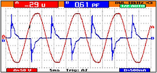
When sinusoidal voltage is applied to a non-linear device, the current acquires a complex, non-sinusoidal waveform. In our age of heavily inductive loads, the current waveform as viewed in the time domain will deviate markedly from the sinusoidal applied voltage waveform. You can see that the waveform is irregular, but it is difficult to know what is going on until you view that same signal in the frequency domain.
In a frequency domain display, amplitude (expressed as power rather than voltage as in the time domain) is plotted on the vertical Y-axis. Frequency rather than time is plotted on the horizontal X-axis. At a glance, the user can see the relative amounts of power at different frequencies. These may appear as slender spikes or as a broader Gaussian distribution depending on the scaling. It is interesting to note that these seemingly discreet harmonics actually have measurable bandwidths, and it follows that there is a whole additional realm of diminishing harmonics with their own associated bandwidths. We must presume that this progression is infinite or that it extends on to a quantum level.
Non-sinusoidal waveforms are caused not only by inductive loads but also, dramatically, by electronic power supply switching circuits including silicon controlled rectifiers, power transistors, power converters and similar solid-state switches. They divide power on a dc bus into short segments with extremely fast rise and fall times (similar to high-frequency signals) for the purpose of controlling motor speed and torque. The result is an electrical environment rich in harmonics.
The progression of harmonics have amplitudes that diminish as frequency rises until, viewed in the frequency domain, the harmonic signals are lost below the noise floor. Each of these harmonics adds to the fundamental, creating a highly complex waveform that deviates significantly from the sine wave in proportion to the amplitudes of the harmonics.
One of the problems with an electrical environment rich in harmonics is that certain classes of electrical equipment, notably ac motors and transformers, thrive on pure sine wave power. When harmonic content rises above a critical level, motors and transformers tend to overheat, damaging winding insulation, which can also be punctured by high-frequency spikes. Fast rise and fall times in these complex waveforms set the stage for run-away capacitive and inductive effects. Harmonics can feed back upstream into the power distribution network, affecting nearby electrical equipment.
Another aspect in harmonic propagation within an electrical distribution system involves triplens, which are harmonics that are multiples of three of the fundamental. Their phase displacement is zero degrees. Consequently, they circulate in a three-phase Y-system between the phase and neutral, or ground.
Phase and negative harmonics cancel out, but triplens are additive in the neutral conductor, which if it is not purposely oversized, will overheat. Besides installing oversized neutrals, which in a retrofit can be quite costly, other approaches are available.
The vast majority of harmonic currents found in ac electrical lines are odd-order harmonics (third, fifth, seventh, etc.) The fifth and eleventh harmonics are of particular concern because both have what’s called a negative sequence: When a voltage containing the fifth or eleventh harmonic is applied to a three-phase motor, the motor will attempt to turn in reverse direction, creating a negative torque.
To compensate for this negative torque, the motor must draw additional fundamental current. This additional current, in turn, can cause overheating and/or the tripping of over-current protection devices. One major source of fifth, seventh, and eleventh harmonics is the six-pulse adjustable speed drive. There are also twelve-pulse drives which eliminate the fifth and seventh harmonics, but they still generate eleventh and thirteenth harmonics.
To begin, a survey should be conducted to find the source of offensive harmonics. The power supply can be monitored using an oscilloscope in FFT mode, a spectrum analyzer or specialized test equipment to determine if the offending source is inside or outside the facility, if it happens at certain hours of the day, etc.
One approach to mitigating harmonics would be to filter out the bad harmonics using resonant circuits. But when large amounts of power are involved, this method would not be economical. A common solution is to add power factor correction capacitance to the load. These devices can be switched on as needed, either automatically or manually. Synchronous ac motors, while more expensive than asynchronous (induction) motors, have the advantage of reducing the overall power factor.

Leave a Reply
You must be logged in to post a comment.