Multi-domain signal analysis is blurring the line between real-time oscilloscopes and real-time spectrum and signal analyzers.
Fernando Gomez, Tektronix Inc.
Multi-domain signal analysis is enabled by advanced oscilloscope features such as 12-bit ADC, digital down conversion (DDC), and flexible channel inputs where each can be either analog or digital. As Signal Integrity (SI) and Power Integrity (PI) engineers know, real-time oscilloscopes will provide frequency domain information by executing a Fast Fourier Transform (FFT) having accuracy and resolution that are direct functions of the sample size/record length. Unfortunately, as the FFT is a post-acquisition operation, there is no practical way to understand the shape of the frequency response relative to the time span during which the analog signal was acquired.
Finally, real-time spectrum analyzers (RTSAs) add real-time performance and include VSA analysis plus trigger capabilities as well as time-resolved analysis of amplitude, frequency and phase over time.
These frequency domain instruments can provide the information needed. However – significant limitations must be acknowledged: Acquisition bandwidth is limited mostly to 1 GHz, and these instruments are limited to a single channel so they cannot look at multiple RF signals simultaneously or correlate to other signals in the system
Of course, real-time oscilloscopes can address these limitations with wideband capture, multi-channel operation and, in some cases, provide time-correlated multi-domain operation. So should scopes be used for RF work?
Is there enough dynamic range to capture the signal’s full energy content? Oscilloscopes are typically limited by the bit depth/vertical resolution of the ADC. RF signal analyzers normally feature 12-16 bits ADC resolution, at narrow bandwidth captures – up to 1 GHz. When wider bandwidth is required, however, the dynamic range is compromised. Thus there must be a tradeoff between high vertical resolution and bandwidth coverage.
How deep is the channel memory? In a VSA or RTSA, memory is efficiently used because the RF signal is sampled and down converted, resulting in fewer samples stored while preserving the frequency content of the signal. An oscilloscope, on the other hand, uses direct sampling of the RF signal. It can oversample at multiples of the fundamental frequency to ensure adequate frequency coverage, but the consequence of storing tightly spaced sample points is that the memory fills out quickly. So only short time spans of the signal can be captured.
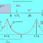
What about preselection? RTSAs and VSAs usually incorporate preselection, or the ability to filter out second and higher order images from the acquired spectrum, at their front ends (FEs). However oscilloscopes don’t normally feature this capability, and preselection is not generally supported at higher frequencies in either class of instruments.
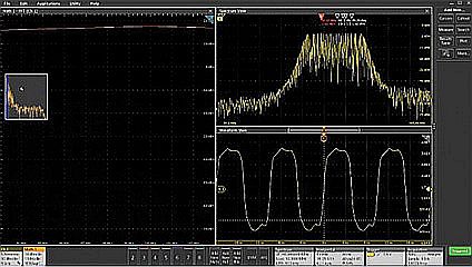
We will consider a simple RF signal measurement using a real-time oscilloscope. Because oscilloscopes capture and display waveforms by default in the time domain, we will make use of an FFT (usually available as a math function) to obtain the frequency domain representation of the signal. In this case, we will be acquiring a clock with a nominal frequency of 98 MHz.
First we display a few cycles of this clock signal in the time domain and compare them with the FFT display with the same center frequency and span. Here, the FFT provides little to no information because the resolution of the FFT is inversely proportional to the length and time of the vector. This means the only way to realize higher resolution is by acquiring a higher number of samples. Doing so provides a spectrum that looks good, but the time domain view is not particularly useful. Actually the time domain view and the frequency domain views cannot be optimized simultaneously!
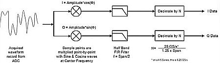
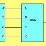
How do we resolve this limitation? Let’s consider a digital down converter (DDC). The DDC numerically mixes the ADC samples down to baseband– in other words, it removes the carrier from the signal, leaving the signal containing the information around dc, or baseband. The baseband data is formatted as I (in-phase) and Q (quadrature) component data.
As data comes from the ADC, the numerical clock oscillators “project” the signal into two parallel processing paths. I and Q data points are represented in the phasor diagram, where the length of the vector is its magnitude and the angle is its phase.
By storing I and Q in memory, we can find out what the spectral content of the signal (magnitude and phase) is at any point in time. Moreover, this I and Q data is recorded into memory in parallel with the ADC (time-domain) data, and the storage requirements are much smaller compared with the ADC data.
At this point, the DDC data is time-correlated to the ADC data. The DDC only needs a sample rate sufficient to cover the bandwidth of the information signal (IF). In conclusion, by “basebanding” or downconverting the signal we obtain the benefit of larger, deeper storage of RF content with significant lower memory requirements – as DDC data samples will be much further apart in time.
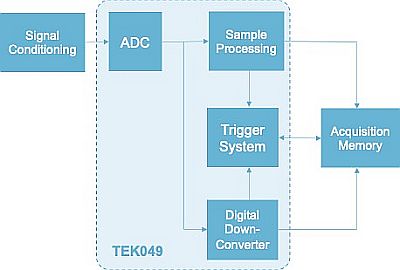
Suppose we now go one step further and incorporate the numerical DDC into the acquisition hardware. Then I and Q data, along with the ADC data, is acquired in every channel and becomes available to the acquisition memory and the trigger system. By placing the DDC and ADC data into memory, we now have the two data sets correlated in time.
Additionally, the spectrum processing vector (time required to capture the frequency domain signal) can be managed independently of the ADC-sampled data. This is available in every channel, with the same or different center frequencies.
To summarize, incorporation of the DDC in the acquisition ASIC resolves the issue of optimizing the view of time and frequency domain signals. It also allows for a simultaneous, time-correlated time and frequency domain capture. Moreover, it makes possible independent acquisition settings and controls in each domain.
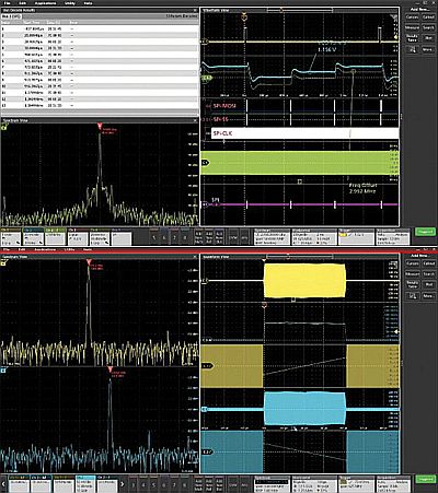
So what does multi-domain, time-correlated signal analysis mean at the system level? The answer is a full, 360° signal analysis via any combination of analog and digital signals, parallel and serial buses, math waveforms, and RF signals and triggers. All of these signal inputs can be analyzed and measured in a time-correlated way with independent adjustments to optimize their analysis and viewing.
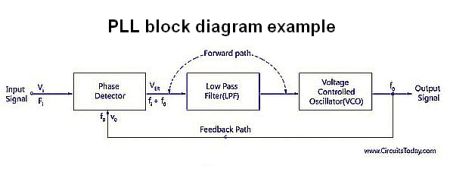
In a nutshell, PLLs are used for the generation of an output signal, the frequency of which is synchronized (locked) to that of a reference input. As different clock frequencies can be obtained with these control loops, PLLs are increasingly used in microcontrollers to manipulate and control the frequency of clock signals.
The basic PLL circuit involves a phase detector at the input, a low-pass filter (LPF) and a voltage controlled oscillator (VCO) at the output, which feeds an error signal to the phase detector, thus completing the loop. Suppose we capture output signal with an oscilloscope having dual ADC and DDC signal paths. One can now investigate the relationship between the analog VCO tune voltage and the transient changes in frequency of the time domain signal. And this analysis can take place in sync with the I and Q sampled data (actually demodulated, or down-converted to baseband), and also at any location over the entire time domain waveform acquisition.
Information across signal buses, time domain and RF traces can be analyzed in sync, and the behavior of the control signals can be validated to determine correct operation.
In a nutshell, Tektronix innovations in Real-Time Oscilloscopes allow for mix-and-match combinations of signal sources for the signal input with the FlexChannel system. This system enables simultaneous time and frequency domain signal capture. It does so by introducing a DDC in the signal acquisition ASIC on every channel and with independent control of the time and frequency domain settings.
As design complexities incorporate analog, digital and RF signals, multi-domain analysis is the perfect fit for design/validation engineers with analog/time domain and RF/frequency domain backgrounds alike.

Leave a Reply
You must be logged in to post a comment.