Differential calculus is the study of rates at which quantities change. To find the derivative of a waveform at a specific point, we draw a tangent line through the point. The slope of the line, Δy/Δx, equals the derivative of the function at that point.
Integral calculus quantifies the area bounded by a curve and the X-axis. The integral is usually stated as the area under a curve. However, the area above the X-axis adds to the quantity and the area below the X-axis subtracts from it.
Integration and differentiation can be demonstrated in a digital storage oscilloscope such as the Tektronix MDO3000. First, with a BNC cable connecting Aux Out on the back panel to the Analog Channel One input on the front panel, press Default Setup. Then press AFG so the default Sine Wave appears in the display. Press the soft key associated with Waveform in the horizontal AFG menu and use Multipurpose Knob a to select Square Wave. Press Menu Off.

Press the red Math button on the front panel, then the soft key associated with Advanced Math in the horizontal Math menu. In the vertical Advanced Math menu, press the soft key associated with Edit Expression. Press the soft key associated with Clear in the horizontal Edit Expression menu. Now the available expressions are no longer grayed out.
Turn Multipurpose Knob a to select Intg (.
Press Enter Selection. Turn Multipurpose Knob a to select Channel One. Again press Enter Selection. Turn Multipurpose knob a to select ). Push OK Accept.
The integrated Square Wave is displayed.
The interesting thing to see in integration is that amplitude is multiplied by time, just as to find the area of a rectangle, height is multiplied by width. Integration sometimes provides a more realistic view of a real-world situation, which is why it is often used in statistics, physics and many other fields of knowledge.
To demonstrate differentiation in the Tektronix MDO3000 oscilloscope, repeat the above steps, substituting differentiation for integration:
Press the red Math button on the front panel, then the soft key associated with Advanced Math in the horizontal Math menu. In the vertical Advanced Math menu, press the soft key associated with Edit Expression. Press the soft key associated with Clear in the horizontal Edit Expression menu. Now the available expressions are no longer grayed out.
Turn Multipurpose Knob a to select Diff(.
Press Enter Selection. Turn Multipurpose Knob a to select Channel One. Again press Enter Selection. Turn Multipurpose knob a to select ). Push OK Accept.
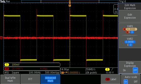
The differentiated Square Wave is displayed.
The derivative of a function at a given input is the rate of change at that point. When we are working in the time domain, that is a point in time. Because the rates of change of the rising and falling edges of a square wave are enormous, the derivatives as shown in Cartesian co-ordinates are high vertical lines.
As a quick review, the generic form of the differential equation is y = f(x). For a linear equation, the slope is a straight line. There are two real numbers, m and b, where y = mx + b. The slope is denoted m and the relevant equation is m = Δy/Δx.
Nonlinear functions, since they are represented in Cartesian co-ordinates or seen in the oscilloscope time-domain display as a curve, do not have a fixed slope. But the tangent to a point on that curve, a single instant in time, does have a slope and can be expressed by a linear equation. Thus, when f(x) = x2, f ‘ (x) = 2x.
The most straightforward way of devising integrator and differentiator circuits is by means of op amps with reactive components in their feedback circuit. Reactive components in the feedback loops of an op-amp circuits cause the output to respond to changes in the input voltage over time. The integrator produces a voltage output proportional to the product (multiplication) of the input voltage and time; and the differentiator produces a voltage output proportional to the input voltage rate-of-change.
 A simple differentiator consists of an op-amp circuit which measures a change in input voltage by measuring current through a capacitor and outputs a voltage proportional to that current. The right-hand side of the capacitor stays at 0 V due to the virtual ground effect on the op amp inputs. Therefore, capacitor current arises only from the change in the input voltage. A steady input voltage won’t cause a current through the capacitor, but a changing input voltage will.
Capacitor current moves through the feedback resistor, producing a resistor voltage drop which is the same as the output voltage. A linear, positive rate of input voltage change will cause a steady negative voltage at the op-amp output. Conversely, a linear, negative rate of input voltage change will cause a steady positive voltage at the op-amp output. This polarity inversion from input to output arises from the input signal being sent (essentially) to the inverting input of the op-amp. The faster the rate-of-voltage-change at the input, the greater the voltage at the output.
The formula for determining voltage output for the differentiator is:

In an integrator, the op-amp circuit generates an output voltage proportional to the magnitude and duration that an input voltage has deviated from 0V. Equivalently, a constant input signal would generate a certain rate-of-change in the output voltage: differentiation in reverse.

 As before, the negative feedback of the op-amp ensures that the inverting input stays at 0 V. If the input voltage is exactly 0 V, no current flows through the resistor, and the capacitor doesn’t charge, so the output voltage doesn’t change.
Application of a positive voltage to the input causes the op-amp output to fall negative at a linear rate in an attempt to change the voltage across the capacitor to maintain the current established by the voltage difference across the resistor. Conversely, a constant, negative voltage at the input causes a linear, rising voltage at the output. The output voltage rate-of-change will be proportional to the value of the input voltage.


Interesting. In signal processing of Giger counters and the PMT output of scintillation meters, the first step is differentiation. For PMT Scintillation detectors the amplitude of the differentiated pulse is used to measure the energy of the detected event and a histogram of multiple events becomes a spectrum of the decay energy modes of the sample.
Can the oscilloscope be programed to differentiate, peak detect, and then accumulate a histogram of the peaks?
What might be the fastest count rate?