Characterizing the wireless devices that make up the Internet of Things (IoT) demands precision sourcing and measurement.
Robert Green
Keithley Instruments, a Tektronix Company
A recent informal survey of more than 1,600 experts conducted by the Pew Research Center’s Internet & American Life Project on the future of the Internet suggests that, within a decade, the growth of The Internet of Things (IoT), including a growing array of embedded wireless devices, will revolutionize the way we live. They foresee the IoT expanding to network billions or trillions of wireless devices.
IoT wireless devices must be small, power efficient, and highly reliable. Minimizing power consumption to maximize operating life is a critical requirement for designers. However, determining device power consumption has numerous challenges. Those challenges are the need to measure with sensitivity and with speed. The instrumentation needed to measure load current must be capable of measuring very low currents when the device is in its sleep and standby modes, but also of making fast measurements during the short period when the device is transmitting data. Measuring low current has one set of requirements; making fast measurements has a completely different set.
IoT devices often have sleep or standby currents of microamps or less. Sometimes, the ability to resolve a tenth of a microamp or even less is required. To produce stable and accurate measurements of these low-level sleep mode or standby mode currents, the instrumentation will generally make many measurements over a long measurement interval in order to average out electrical noise created in the device and noise from the external environment. Filtering can also be used to ensure quality measurements.
A measurement period that extends over a number of AC power line cycles along with filtering can result in a measurement time well into the seconds and often tens of seconds. Making an accurate low sleep or standby current measurement often requires some measure of sacrifice in measurement speed.
Measuring quickly to capture peak load currents
In addition to making slow, sensitive measurements of the sleep or standby currents of IoT devices, the instrumentation must make very fast current measurements when an IoT device is active. The challenge is to measure a load current pulse that may be present for only a few hundred microseconds. The instrumentation must respond quickly to make a measurement in a very short time interval. In this situation, one must sacrifice some measurement accuracy and resolution to get speed.
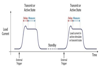
Figure 1 shows a typical load current profile for an IoT device. In sleep mode, the current is extremely low, but when the device is transmitting, the load current will rise dramatically for a short time. To measure this current, the instrumentation must respond to control signals that indicate when the device is transitioning into the active state so that the instrumentation can initiate the high-speed measurement.
Quite often, there will be some overshoot before the load current reaches a stable value. If this happens, then the instrumentation needs to be able to delay the onset of the measurement as shown. Once the measurement begins, it must be fast enough to be completed before the load current starts to decline. If the measurement takes too long, the result will be inaccurate.
Instrument options
Because the requirements for making accurate low-current measurements and fast high-current measurements are so different, multiple instruments are often needed. It would be possible to connect a sense resistor in series with the test lead that connects a power supply to the device-under-test and measure the voltage across the sense resistor with a DMM. If the sense resistor were small enough, it would add only a small additional error in the load current measurement. If the load resistor was too small, however, the DMM might not be sensitive enough to measure the low sleep mode or standby mode currents accurately.
To capture the short, higher current active-mode load current, the DMM would need to make the measurement very quickly and start those measurements at just the right time. The DMM would have to be capable of responding to external trigger signals to start the measurement, and the DMM would also need to delay the measurement start time to ensure the measurement was made during the appropriate portion of the load current pulse. In addition, the DMM would have to make the measurement fast enough before the load current returned to its standby state.
More often than not, an oscilloscope would be necessary to capture the magnitude of the short, active-mode load current pulses. This would also require using a sense resistor in the circuit. Although this would solve the challenge of measuring the peak load current, oscilloscopes are not designed for sensitive DC measurements, so a DMM or other instrument would be needed for the low-level measurements. To make all the necessary measurements, a power source, a DMM, and an oscilloscope might be required.
A source measure unit (SMU) instrument is another possible solution for this application. They can measure very low currents (down to picoamps or less) accurately; unfortunately, they are not designed to capture short pulses. Also, they are generally low power instruments and so might not have sufficient total power to deliver the peak current necessary to characterize a device that draws a large amount of peak power such as an implantable defibrillator. In addition, because of their extraordinary sensitivity, SMU instruments can be relatively expensive.
Single-instrument solution makes measurements easier
Although it would be possible to make all the necessary measurements with some combination of the instruments described previously with some software to glue it altogether, a better solution would be to use a single instrument. The challenge is that this instrument would need to have a combination of features not normally found in a single instrument. First, it must provide sufficient power to energize a wide range of IoT devices, and second, it must measure both very low load currents and much higher active load currents accurately. Fortunately, such instruments are starting to emerge on the market in the form of precision power supplies.
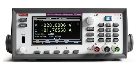
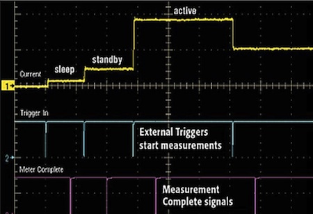
To measure very low standby or sleep mode currents, this new breed of power supply can make DMM-quality measurements with up to 6½ digits of resolution (Figure 2). When making high current measurements, they can capture current pulses as short as hundreds of microseconds. Also, because IoT devices often have a power-up load sequence and a power-down sequence, similar to the one shown in Figure 3, these new instruments are increasingly able to make multiple, synchronized measurements at each state of the power-up or power-down cycle.
Instrument suppliers are now offering general-purpose power supplies with advanced display capabilities, including built-in graphing functions that simplify monitoring the stability of the load current, capturing and displaying a dynamic load current, or viewing a start-up or turn-off load current.
For anyone considering a precision power supply as a solution for this application, if the instrument is going to be used in an automated test system in addition to the designer’s bench, ensuring that it has the LAN, USB, or GPIB interfaces and digital inputs and outputs needed to integrate it with other equipment is essential.

Leave a Reply
You must be logged in to post a comment.