As electronics migrates to higher and higher frequencies, the media routing electronic signals to their intended destinations grow increasingly exotic. This is particularly true as communication technology moves to 5G frequencies which are characterized by millimeter wave transmissions. In this frequency range, engineers are more likely to encounter waveguides and transmission lines rather than ordinary wiring.

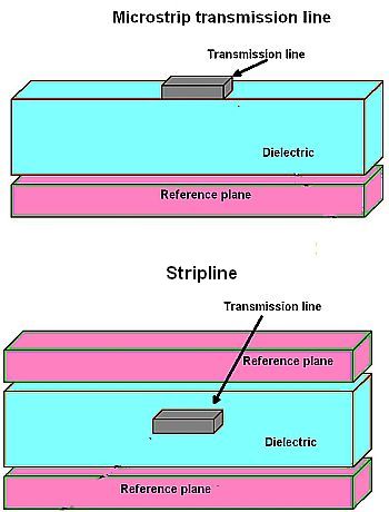
A transmission line is basically two or more conductors separated by an insulating medium. The insulating medium can be circuit board material, as in the case of microstrip lines. In the case of coax cable, the insulating media is the plastic material separating the center conductor from the outer shield.
The normal operating mode for a transmission line is TEM (Transverse Electromagnetic) or quasi TEM mode where neither the electric nor the magnetic field is in the direction of propagation. But a point to note is that all signal frequencies can pass through a transmission line.
A waveguide is a special form of a transmission line. Metal waveguides are typically one enclosed conductor filled with an insulating medium, normally air. More specifically, waveguides are typically hollow metallic tubes of uniform cross section for transmitting electromagnetic waves via successive reflections from the tube’s inner walls. Thus transmission lines like coax have a center conductor. Waveguides don’t. The tube wall provides distributed inductance. The empty space between the walls provided distributed capacitance.
Waveguides handle TE (Transverse Electric) or TM (Transverse Magnetic) mode transmission—they can’t support TEM mode. In TE mode there is no electric field in the direction of propagation. TE mode transmissions are sometimes called H modes because there is only a magnetic field along the direction of propagation. In the TM mode the magnetic field is transverse to the direction of propagation while the electric field is normal to the direction of propagation.

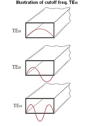
Thus where transmission lines can pass signals of all frequencies, waveguides can only pass frequencies above the TE or TM mode cut off frequency, the lowest frequency the waveguide can pass. The lowest frequency, in turn, relates to the longest half-wavelength that fits in waveguides’ biggest dimension. The exact mechanics for the cut-off frequency of a waveguide vary depending on its shape. Signals can progress along a waveguide via a number of modes. But the dominant mode is the one having the lowest cut-off frequency. For a rectangular waveguide, this is the TE10 mode. The equation for the cutoff frequency fc in a rectangular waveguide is fc = c/2a where c = the speed of light in the waveguide, m/sec; a = the largest internal dimension of the waveguide, m. The equation for a circular waveguide is fc = (1.8412×c)/(2πa) where c is as before and a = the waveguide’s internal radius, m.
Waveguides also differ from other transmission lines in transmission qualities. All waves travel through waveguides via reflections from the walls; in other transmission lines there are relatively few reflections during normal operating modes. A transmission line has a characteristic impedance but waveguides have a wave impedance. Thus circuit theory predicts how signals propagate through non-waveguide transmission lines; but field theory predicts propagation through waveguides. And if you want to transmit high power in a transmission line, you use a larger wire; but the dimensions of waveguides are determined by the propagation modes to be allowed, not by power levels.
Finally, in ordinary transmission lines waves don’t disperse, but they do in waveguides.
Waveguides are often the preferred method of handling microwave frequencies because microwave energy experiences less loss when traveling through waveguides than when traveling through coax. Additionally, waveguides are relatively easy to make and can handle power levels in the kilowatt range.


Leave a Reply
You must be logged in to post a comment.