Use of electronics and capacitive-based position sensing have transformed the caliper, a fundamental and essential instrument of precision linear-dimension measurement.
Making precise measurements across small distances of up to several inches or tens of centimeters is an obvious and fundamental requirement of modern metrology, research, and mass production. But how can that be done accurately, reliably, and easily? The answer is with the caliper which comes in several versions including the all-mechanical basic, Vernier, and dial-readout calipers and, for the past few decades, the easy-to-use digital-readout caliper. This FAQ will look at these accurate yet inexpensive digital calipers which have transformed the challenge of making short, linear-distance measurements.
Q: How was this measurement made before electronics?
A: It was done by using a micrometer or a caliper. The micrometer, Figure 1, was made possible due to the development of precision thread-cutting machines, one of the critical steps which both spurred and benefited from the industrial revolution of the 1800s. A micrometer typically has a maximum span of one or two inches (2.5 to 5 cm).
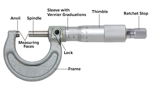
Q: How does the micrometer work?
A: It uses a tight-pitch screw thread (typically, 40 threads per inch) and rotating barrel with gradations to indicate turns and position. The micrometer is effective but costly, but also impractical for many types of measurements (especially inside small-diameter circles) due to cost, configuration, or the need for many different versions for the various items to be assessed.
Q: Then what is a caliper?
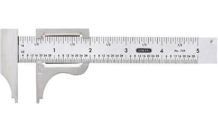
A: The basic caliper (Figure 2) has existed in many forms since ancient Roman times, either as a compass-style instrument with a marked scale along an arc near the hinge point, or as two graduated rulers sliding alongside each other. It’s easy to use but can only offer relatively coarse precision at best, on the order of 0.1 inch (0.254 mm), which is insufficient for most modern uses. A caliper has a typical maximum span of six or 12 inches (about 15 cm to 30 cm).
Q: Then what’s a Vernier caliper?
A: The limited performance of the basic caliper was greatly improved with the development of the Vernier caliper, Figure 3. It increased performance by a factor of at least 10× while adding very little to the mechanical complexity or cost of the basic unit – a very worthwhile tradeoff. It was invented by Pierre Vernier (1580 – 1637), a French engineer and mathematician working in cartography and surveying.

Q: How does the Vernier caliper work?
A: The simple but non-intuitive concept uses two graduated scales: one is a main, standard scale, supplemented with a second scale which slides parallel to it. The gradation markings of second scale have a pitch which differs slightly from the main one; for example, if the main scale has 10 division to the inch, the second scale might have 11 divisions, see Reference 3.
Q: How does this help readout precision?
A: This dual-pitch scale enables readings to be made to a fraction of a division on the main scale, with any change in position visually enhanced by a factor equal to the inverse of the relative pitch difference. Thus, if the difference is 10% (10/11 gradation pairing), the improvement will be a factor of 10×. While it is possible in theory to go to higher factors such as 20×, the reality is that it is both difficult to read and also yields false precision, because the finer gradations are not as precisely spaced as they need to be, due to tolerances and imperfections in the gradation-ruling process.
Q: What was the use of the Vernier caliper?
A: Reading the vernier scale takes practice and careful attention. However, it was the only possible way to get higher precision before our modern metrology was developed and served its purpose for several centuries. You could buy a Vernier caliper into the 1980s for $15 for a basic unit to about $100 for one made of better materials and with greater repeatability and less mechanical “slop.”
Q: What came after the Vernier caliper?
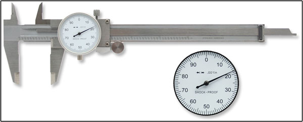
A: Another enhancement to the basic caliper was the dial readout, Figure 4. This caliper has an indicator dial with needle pointer with which the user could easily read out value, usually only the critical last-position, least-significant, most-precise digit of the reading (obviously the most important one, in most cases). It uses a fine-tooth rack-and-pinion assembly along the caliper’s frame. As the caliper slide is extended or shortened, the tiny pinion rotates on the track, and this rotation is connected via gearing to the indicator needle.
These are still mechanical calipers with analog readouts, of course. Part 2 of this FAQ looks at a marvel of modern, low-cost metrology: the electronic digital-readout caliper.
References
- “A Brief History of the Micrometer,” (Mitutoyo)
- “Tech Essential: Outside Micrometers” (MSC Industrial Direct Co.)
- “How to read a vernier (caliper), ” (Autodesk, Inc.)
- “Small Tool Instruments,” (Mitutoyo)
- “Pierre Vernier,” MacTutor History of Mathematics (School of Mathematics and Statistics, University of St Andrews, Scotland)
- FDC1004: Basics of Capacitive Sensing and Applications
- The Advantages of Capacitive vs Optical Encoders

Leave a Reply
You must be logged in to post a comment.