• Skip to primary navigation
  • Skip to main content
  • Skip to primary sidebar
  • Skip to footer
  • Advertise
  • Subscribe

Test & Measurement Tips

Oscilloscopes, electronics engineering industry news, how-to EE articles and electronics resources

  • Oscilloscopes
    • Analog Oscilloscope
    • Digital Oscilloscope
    • Handheld Oscilloscope
    • Mixed-signal Oscilloscope
    • PC-based Oscilloscopes – PCO
  • Design
  • Calibration
  • Meters & Testers
  • Test Equipment
  • Learn
    • eBooks/Tech Tips
    • FAQs
    • EE Training Days
    • Learning Center
    • Tech Toolboxes
    • Webinars & Digital Events
  • Video
    • EE Videos
    • Teardown Videos
  • Resources
    • Design Guide Library
    • Digital Issues
    • Engineering Diversity & Inclusion
    • Leap Awards
    • White Papers
  • Subscribe
You are here: Home / New Articles / Does a planet have a capacitance?

Does a planet have a capacitance?

March 12, 2021 By David Herres Leave a Comment

The self-capacitance of Earth is approximately 710 μF, assuming the free-space dielectric to be a vacuum. The capacitance of Mars is 378 μF. At first glance, it may not be clear where these figures comes from or how a planet can have a capacitance. And if a planet has a capacitance, might it also have an inductance, and if so, might it also have a resonant frequency? The answer is yes to these queries. Interestingly, it may have been Nicola Tesla who first pondered these issues.

The capacitance of a planet comes from the equation for the capacitance of a sphere. The capacitance C of a sphere of radius R is given by C=4πεR . Here ε is the permittivity of the dielectric medium. Given that most capacitors involve a potential difference between two plates, you might wonder where the other plate is when we’re talking about a sphere. The answer: The other conductor is taken to be at infinity. So the permittivity in the equation becomes ε0, the permittivity of free space. (Probably a good estimate because most of the area between earth and infinity is indeed occupied by free space.) The radius of earth = 6,378 km. Thus the capacitance of earth C= 4π×8.854×10-12 ×6,378×103 = 7.096×10⁻⁴ Farad, or 710 μF. Because Mars has a radius of 3,400km, its capacitance is smaller. You can use the equation for the capacitance between two spheres, and make a few assumptions, to come up with the estimate of the capacitance between the earth and the Moon as 159 μF.

tesla
Tesla’s Colorado Springs laboratory (Wikipedia).
Tesla got interested in the earth’s electrical properties through his wireless energy transmission experiments at his Shoreham Experimental Station in Long Island, N.Y. and in Colorado Springs, Col. The discussion about his work often involves a Schumann cavity. It’s clear that Tesla had somewhat figured out the concept of the Schumann Cavity though it was not formally conceived until the 1950s. Here’s the idea: The atmosphere is actually a weak conductor. There is a cavity defined by the surface of the Earth and the inner edge of the ionosphere 55 km up. The Schumann resonances are quasi standing wave electromagnetic waves that exist in this cavity. But to see them, they must be ‘excited’ by electrical activity in the atmosphere, as from intense lightning. They happen at frequencies of 7.8, 14, 20, 26, 33, 39 and 45 Hz, with a daily variation of about ± 0.5 Hz.

Standing waves (modes-like) are formed in the cavity which functions like a wave guide. By solving the classical Maxwell Equations one can arrive at the conclusion that both longitudinal (proportional to the cavity mean radius) and transverse (proportional to the cavity height) modes (or standing waves) are present in the cavity. Besides the ELF (0-100 Hz) Schumann frequencies, there are also VLF (0-10 kHz) resonances as well. Lightning (or man-made) discharges can excite these modes, especially the 7.83 Hz mode.

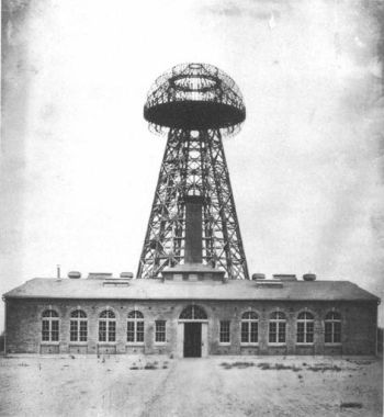
Tesla made the first documented observations of global electromagnetic resonance at his Colorado Springs lab in 1899. The observations led to his idea of wireless energy transmission. Calculations based on his experiments led Tesla to deduce the resonant frequency of the earth was about 8 Hz, i.e. a Schumann resonance frequency.

It turns out that wireless transmission employing Schumann resonances isn’t really practical. One reason is that the cavity between the earth and the ionosphere has a small Q-factor (ratio of electric field energy stored in the cavity per cycle/average power input). Nevertheless, Tesla at Colorado Springs disturbed the earth’s electric field (or blanket) with extreme electric discharges, trying to excite the earth-ionosphere cavity. He determined that time required for a transmitted pulse to travel from the point of transmission to the antipode (the point on Earth’s surface diametrically opposite) and back is 0.08484 seconds, yielding a fundamental earth resonance frequency of 11.786892 Hz.

tesla
Tesla’s Wardenclyffe plant on Long Island in 1904 (Wikipedia).
To further test his theories, Tesla moved to the Shoreham Experimental Station, the site of the iconic 187-ft tower often associated with his name. The tower was actually a capacitor. Tesla’s idea was to electrically couple two distant elevated terminals in a way resembling the transfer of electrical energy between two closely spaced capacitor plates. But the distances involved greatly exceeded the one-sixth or one-half wavelength of the transmitted frequencies typical of ordinary capacitor plates.

Tesla pursued two different operating principles for wireless transmissions. One was called the open circuit or earth resonance method. Here a Tesla coil transmitter creates a local disturbance in the earth’s charge. The source operates at some harmonic of the earth field-resonance, 11.78 Hz. The receiver Tesla coil is passive and is sympathetically activated in a way analogous to a tuning fork vibrating in sympathy with another nearby fork at the same frequency that has been struck by a hammer.

Tesla’s second method was atmospheric or closed-circuit conduction. electrostatic induction instead of true conduction. It employed a Tesla coil transmitter creating an ionized path connecting the transmitter upper atmosphere and an ionized path connecting the upper atmosphere back down to receiving Tesla Coil. The circuit is closed via current flowing back to the transmitter through the earth.

More specifically, an oscillating RF electric field forms a plasma state in the high-voltage (10M to 12M V) capacitor plate. An ionizing beam of ultraviolet radiation was also to be used to form a high-voltage plasma transmission line in the upper troposphere to create a conductive path. The process relied on plasma waves developing in the ionized region between the two terminals (electrostatic waves or magneto-hydrodynamic waves). The ionization of the space between the two “capacitor” plates in turn would permit ELF and VLF waves to flow between the two locations.

There were theoretical issues with the earth resonance method. They involve the scalar derivatives of the electromagnetic potentials. There don’t appear to be any problems with the physics of atmospheric conduction, but the scales involved may make it impractical. However, an MIT spinout called Witricity is said to be investigating Tesla’s ideas about wireless transmission.

You may also like:

  • 5G
    Will 5G be lethal?
  • rental instruments
    The modern economics of renting test instruments
  • no you can't detect ghosts with a gauss meter
    No, you can’t detect ghosts with a gauss meter
  • leland-teschler-and-oscilloscope-feat
    No nostalgia for old test instruments
  • microphone scope trace
    A simple human voice display on the oscilloscope

Filed Under: FAQ, Featured, New Articles

Reader Interactions

Leave a Reply Cancel reply

You must be logged in to post a comment.

Primary Sidebar

Featured Contributions

Why engineers need IC ESD and TLP data

Verify, test, and troubleshoot 5G Wi-Fi FWA gateways

How to build and manage a top-notch test team

How to use remote sensing for DC programmable power supplies

The factors of accurate measurements

More Featured Contributions

EE TECH TOOLBOX

“ee
Tech Toolbox: 5G Technology
This Tech Toolbox covers the basics of 5G technology plus a story about how engineers designed and built a prototype DSL router mostly from old cellphone parts. Download this first 5G/wired/wireless communications Tech Toolbox to learn more!

EE TRAINING CENTER

EE Learning Center

EE ENGINEERING TRAINING DAYS

engineering
“test
EXPAND YOUR KNOWLEDGE AND STAY CONNECTED
Get the latest info on technologies, tools and strategies for EE professionals.
“bills

RSS Current EDABoard.com discussions

  • Why need use TOPmetal Stacking?
  • Monte-Carlo simulation error on ADE-XL
  • Snooping Around is All
  • Identification of a 6 pin smd chip (sto-23-6) marked E2
  • Dynacord enter protect

RSS Current Electro-Tech-Online.com Discussions

  • Fun with AI and swordfish basic
  • using a RTC in SF basic
  • Does US electric code allow branching ?
  • Faulty heat air gun (dc motor) - problem to locate fault due to Intermittent fault
  • Sump pit water alarm - Kicad 9
Search Millions of Parts from Thousands of Suppliers.

Search Now!
design fast globle

Footer

EE World Online Network

  • 5G Technology World
  • EE World Online
  • Engineers Garage
  • Analog IC Tips
  • Battery Power Tips
  • Connector Tips
  • DesignFast
  • EDA Board Forums
  • Electro Tech Online Forums
  • EV Engineering
  • Microcontroller Tips
  • Power Electronic Tips
  • Sensor Tips

Test & Measurement Tips

  • Subscribe to our newsletter
  • Advertise with us
  • Contact us
  • About us

Copyright © 2025 · WTWH Media LLC and its licensors. All rights reserved.
The material on this site may not be reproduced, distributed, transmitted, cached or otherwise used, except with the prior written permission of WTWH Media.

Privacy Policy