Most engineers think they’ve minimized the chance of nasty surprises around the test bench when they’ve grounded their instruments and perhaps kept one hand in their pocket when working around high voltages. That said, there remain electrical hazards that are less obvious. They involve the electrical wiring and the environment around the lab.
To begin, in the wall space at the rear of the bench, receptacles should be available to supply electrical power appropriate for the work contemplated. Separate, labeled receptacles should offer options of a 14 AWG, 15-A branch circuit to limit arc flash, terminating in a GFCI; also, several 12 AWG, 20-A non-GFCI receptacles should be available. All should be controlled by a single 20-A kill switch. Don’t forget a fire extinguisher and smoke detector far enough back so soldering at the bench won’t set it off.
Beware of electrical wiring that is close (within 50 ft) of an indoor distribution transformer–you might check to see if there is a transformer vault on the other side of the shop wall. Because of the low-impedance power source and branch circuit wire, a ground fault caused by a small nick in an ungrounded conductor can cause an intense arc flash accompanied by a loud explosion that can be heard throughout the building.
Technicians and lab workers should be aware of the general electrical system. It is essential that it is solidly grounded at the entrance panel, and the grounding conductor (green or bare wire) is intact right to your bench. Over-current protection will not function if there is a break in this wire or if it is undersized.
If the floor is concrete and therefore grounded, a rubber mat or wooden platform in the work area will reduce the severity of shock. A wooden stool is helpful as well, although it should be remembered that the human body always has a certain ground potential. You are not a light bird that can perch with impunity on a high-tension distribution line.
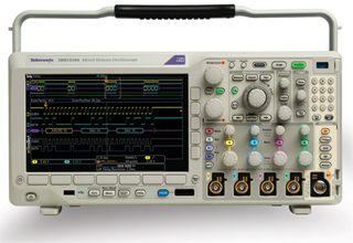
There is a hazard intrinsic to improper bench-type instrument usage. A line-powered oscilloscope contains some normally non-current-carrying conductive metal parts, and they are ultimately connected to the solidly-grounded pole-mounted utility transformer center tap in the secondary winding. When you plug an oscilloscope probe into one of the analog channel inputs, you are connecting the ground return lead to that center tap via a low-impedance current path. Consequently, if the ground return lead–the end with the alligator clip–is connected to a voltage that is referenced to but floats above ground potential, a heavy arc fault will arise.
If you are fortunate, the thin conductor that is the probe ground return lead will function as a fuse, burning through and interrupting the circuit before extensive damage to the oscilloscope, device-under-test, or user is inflicted. It does not matter if the oscilloscope power switch is off or a GFCI or breaker is open. Grounding is maintained via the green grounding conductor, the white grounded conductor and the main bonding conductor in the entrance panel. And these ground paths bypass any switching and overcurrent protection, which are built into the hot side of the circuit, not the ground return.
So how do you measure and display floating voltages in an oscilloscope? In the most common type of circuit, one side is referenced to and floats above ground, while the other side is solidly grounded. (What makes a line referenced to ground is that the other side is grounded. If neither side is grounded, as in a battery, there is no floating voltage and the oscilloscope can be connected either way without regard to polarity.) In a floating-voltage circuit, the ground return lead must be connected to the grounded side and the probe tip to the hot side. Then, as long as you are within the voltage limits of the instrument, you are OK.
A couple problems remain. Often, when looking at current paths in a printed circuit, at motor terminals or within electrical equipment, it is not possible to determine which side is grounded. Moreover, you have to analyze the utility power at the receptacle to make sure that somewhere along the line, the wires were not crossed, invalidating the color code.
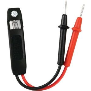
There are instances when the methods for distinguishing between a grounded conductor and a conductor referenced to ground and energized at a higher potential do not resolve the polarity question. Specifically, there’s a problem when both sides of the circuit are referenced to and float above their grounds.
Typically, a center tap is grounded. This type of circuit cannot be measured and displayed by means of a conventional grounded bench-type oscilloscope because a severe fault-to-ground will arise when the probe ground return lead connects to either side of the circuit. This is regardless of whether the instrument is powered up or whether the probe tip is in contact with the other side of the circuit. Here are some examples:
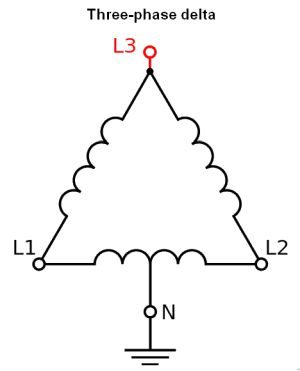
In a variable-frequency drive used to control the speed of a three-phase ac motor, the utility voltage, typically 480 Vac, is rectified to a still higher dc voltage by means of a full-wave rectifier with a center tap. This voltage is conveyed to the inverter section via the dc bus, and technicians often want to view this voltage in an oscilloscope to see if there is excessive ripple, which may be disrupting the inverter. But because both dc conductors are ungrounded (but referenced to ground), such a measurement cannot be performed using a conventional bench-type oscilloscope hookup.
A similar situation exists in a switching power supply. Both output conductors and parts of the internal wiring are referenced to ground and float above it. Similarly, an ordinary residential dimmer switch presents this hazard.
There are several remedies. Some technicians saw off the oscilloscope power cord ground prong. While this may protect against arc faults associated with floating voltages, additional unexpected hazards are introduced down the road because an internal fault or moisture that has entered the enclosure may energize normally non-current carrying conductive parts. The over-current protection at the entrance panel or distribution box will not trip out without grounding conductor continuity.
Another remedy is to use an isolation transformer, either factory made or fabricated by connecting two identical transformers back-to-back, starting with the step-down transformer. The problem here is that an internal ground fault or alternate ground path can negate that strategy.

Thus most technicians use the hand-held, battery powered oscilloscope for floating voltage measurements. All channels in these instruments are isolated from ground, eliminating arc-fault hazards otherwise inherent in these measurements.


The most important rule I learned when employed at Doble Engineering was to keep my hands off of any connection which could pose a risk, as the left arm has veins which return directly to the heart, and it doesn’t take much voltage (~50V) to break down the body’s insulation (the skin) nor much current (~50mA) to stop the heart when it gets there. I thank my lucky stars that this served me while I worked there. We were all required to learn and be regularly re-trained in emergency CPR.