The Local Interconnect Network (LIN) Bus was created to augment CAN Bus, at first in automotive applications and later for industrial use. CAN Bus was developed by Bosch to serialize communication among automotive electrical systems. It is a good candidate where high-bandwidth and advanced error-handling is needed as in automotive engines, where transmission and braking systems are involved.
But automotive engineers soon perceived the need for a less expensive bus system able to handle intersystem communication among less critical components such as power windows, seat controllers, steering-wheel accessories, and so forth. For all these and similar functions, LIN Bus provides an appropriate and economical solution. It does so by reconfiguring the CAN Bus into a lower-bandwidth multiplexed communication system using relatively inexpensive 8-bit microcontrollers with embedded standard serial universal asynchronous receiver/transmitter (UART) techniques.
At present, CAN Bus and LIN Bus work in concert within a vehicle. Additionally, the FlexRay Bus is emerging as a means of handling high-speed synchronized data communications for especially critical areas including active suspension.
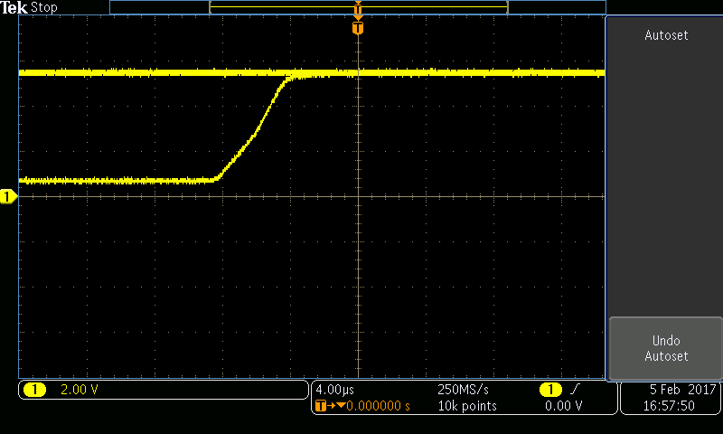
In looking at LIN Bus signals on a scope, the lower level voltage (logic zero) should be less than 20% of battery voltage (typically 1 V) and the upper level voltage (logic one) should be more than 80% of battery voltage. The voltage levels may change slightly when the engine is started. Also, certain scope manufacturers provide add-ons that will decode LIN Bus signals.
Turn signals are one of the common functions wired onto a LIN Bus. The LIN master for this system is often the instrument cluster. The LIN slave is the multi-function switch. When the driver hits the turn signal switch a LIN-Bus message goes to the instrument cluster on the dedicated LIN wire. The instrument cluster might then send a message to a power module that flashes the turn signal bulbs on the vehicle exterior. If the turn signals are inoperative, diagnosis of the LIN connection is easy. Connect the scope to look at the instrument panel data stream. Look for the turn signal switch bussed input. When you switch the lever for a turn, the data should reflect that. If the input does not change then the problem might be in the power, ground, or LIN wiring to the multi-function switch.
Technicians might check the LIN wiring by simply unplugging the slave module and checking the ‘at rest’ voltage of the LIN wire. The master should send out the 7-to-12-V reference. If the wiring to the multi-function switch checks out, the switch may be bad.
Another system generally found on a LIN bus is the tire pressure sensor/transmitter system with a unique transmitter ID in each wheel. A wireless control module communicates with the tire pressure sensors. When the vehicle is driven, all four sensor/transmitters periodically send out signals. To determine each tire position, the wireless control module sends a LIN-Bus message to a trigger module that then produces a signal of about 125-kHz that commands the pressure sensor to produce a constant signal. The wireless control module then determines which transmitter ID responded and tags it to a specific corner of the vehicle.
In LIN Bus, there is a master and one or more slave devices. The message header is made up of a break that signifies the start of a frame, followed by a sync field whose purpose is for clock synchronization within the slave. This is followed by an identifier, which is a six-bit message ID and a two-bit parity field. The message ID consists of a message address. The appropriate slave issues a response to the message, which variously contains between one and eight bytes of data and an eight-bit checksum.
A LIN Bus master device has master and slave tasks. In contrast, a slave device has only a slave task. The master task controls all LIN Bus communication. The standard procedure is for the master to broadcast the identifier throughout the network, whereupon the appropriate slave responds with the required data. The master broadcasts the identifier to the entire network and a single slave replies with the desired data.
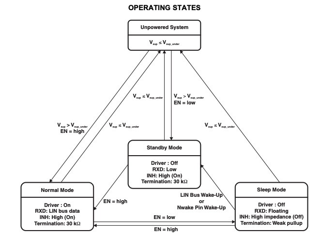
A benefit realized by the LIN Bus is its low-power nature, making it an economical alternative to CAN Bus. One way LIN Bus conserves power is by allowing devices on the bus to enter a sleep state when they are not required to be active. This takes place when the master sends a request frame having its first data byte equal to zero.
Additionally, slaves enter the sleep state when the LIN Bus has been inactive for more than four seconds. And the user can manually put the LIN interface to sleep by setting the LIN Sleep attribute to True. Naturally, there is a means for waking these devices. A wake-up call can come from any node on the bus, either master or slave. To initiate wakeup, the bus must be dominant for a period of time between 250 µsec and 5 msec. The slaves then become aware of the wakeup call and have the ability to interact within 100 msec. At this point in time, the master also becomes ready for action. If the master does not respond, the slave keeps trying until there is a resolution.
An aspect of LIN Bus that makes it more economical and conserves bandwidth is that all messages are initiated by the master, which at times also functions as a slave by replying to its own messages. Consequently, there’s no need for collision detection. The bus also conserves space, power and therefore cost because its masters and slaves may be comprised of simple hardware such as application-specific integrated circuits.
An important feature of LIN Bus that makes it suitable for use in automobiles is its ability to operate at 12 V. Moreover, data is simply conveyed throughout the bus in messages having a fixed form but with lengths that may be altered to fit the circumstances. First the master transmits a break within a header with synchronization and identifier fields.

LIN Bus is intended to complement CAN Bus in areas that are not time-critical and that are relatively fault tolerant. So its physical layer is simple. The master/slave format is implemented by means of a single wire (plus ground). Time-triggered scheduling and bits that are either recessive or dominant characterize this serial communication that is byte oriented, meaning data is sent in single-byte units. The maximum conductor length is just over 130 ft., adequate in automotive and ordinary tractor- trailer applications.
LIN Bus uses six types of frames:
The unconditional frame, if there are no errors, carries signals to all subscribers.
The event-triggered frame relieves the bus of bandwidth burden that would be incurred if polling of all slave nodes were required for every event. Collisions arise when, in a single frame slot, more than one slave task responds to the header. The collision is cleared when the master again requests the event-triggered frame.
A sporadic frame cannot be party to a collision because it is transmitted by the master only as required. It is sent only when the master task knows that it will be received. This collision avoidance is a great thing about LIN Bus because it means conversations can happen more efficiently and with less bandwidth cost.
A diagnostic frame always contains eight bytes of diagnostic or configuration data. It is either a master request frame or a slave response frame. The master diagnostic module decides if it should be sent and the slave diagnostic modules decide how it is to be interpreted.
A user-defined frame may carry any type of information.
A reserved frame is not used in the current LIN Bus implementation.
The whole point of the LIN Bus specification is that it should take over less-than-critical CAN Bus functions where possible and perform them less expensively. One way this happens is by specifying less costly node hardware. The single-wire network is key to this build-over. Network devices are generally microcontrollers with UART capability or dedicated LIN Bus hardware.
To further cut expense, LIN slave nodes employ less costly RC oscillators rather than quartz or ceramic oscillators. To compensate for this reduced accuracy, the sync field contained in the header is used to get clock stability.
On LIN Bus, the two types of devices, master and slave, play different roles in regard to the header and response frame constituents. The header is invariably sent by the master, while the response may be sent by either of these entities.
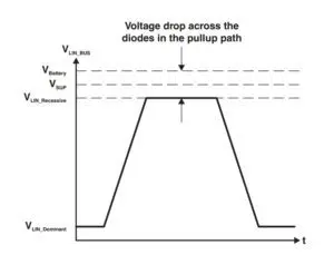
Data, at rates ranging from 1 kbit/sec to 20 kbit/sec, can instantaneously be either recessive (high logic state) or dominant (low logic state).
The header is made up of the following parts:
• Break, which activates all slaves.
• Sync, accomplished by means of the slave’s RC oscillator in conjunction with bit timing provided by the master.
• Inter byte space, which compensates for any jitter that may be on the bus. It is not always used.
• Identifier, which may be either Tx or Rx, depending upon whether it is applicable to the slave transmit or receive function. Its purpose is to order the data flow so multiple transmissions do not occur simultaneously.
Response consists of data or checksum. When data is sent, it may contain anywhere from zero to eight bytes. Checksum is a small sector of data intended to check for errors that may have entered during transmission or storage. The checksum may or may not include the identifier, depending upon the LIN Bus version.
When the master device sends a message, there must be a mechanism that determines which slave, such as a temperature sensor, should receive it. This setup is not uniform in all LIN Bus implementations, so there are proprietary variations. Regardless, identical or similar devices may be connected to a single bus without relying on identification by means of the connector pins or end-of-line programming. NXP, successor to Philips Semiconductor, uses the extra wire daisy chain method while Elmos Semiconductor employs bus shunting. Slaves in these schemes that are auto-addressing must be connected in the same line, but this restriction does not apply to standard slaves.
To summarize, use of LIN Bus to augment CAN Bus offers significant advantages including dissipation of less power, ease of use, readily available components, and reduced wiring.

Thank you
I now have a better understanding
Enjoyed this thoroughly. I cut my teeth on J1587/1708 and J1939 datalinks, and this was great information on the single wire LIN. Thank you!