The Automotive Testing Expo in Novi, Mich. hosted more than 280 exhibitors displaying test & measurement technology relating to EVs, battery testing, calibration, durability testing, and numerous other areas related to the design and development of automotive technology. Another +70 booths made up the colocated Automotive Interiors Expo. Below are a few of the more notable sights we encountered in our time at the event.
How to quantify potholes

Several exhibitors displayed equipment used to gauge vehicle ride qualities. One such device was this wheel force transducer setup at the Michigan Scientific Corp. booth. The transducer takes the form of a wheel hub assembled onto the vehicle wheel. The hub contains four strain gauges positioned around its perimeter. Two of them are circled in green within the nearby image. This particular model also contains an accelerometer residing on the axle axis. The test fixture reads out three forces and three moments as well as accelerations along the X and Z axes. MSC engineers told us the transducers also help determine how well equipment operates under extreme weather and road conditions. Typical parameters determined with this setup include longitudinal force, lateral force, vertical force, camber moment, wheel torque, steer torque, as well as wheel position and speed.
Even the Raspberry Pi has a role in automotive networks
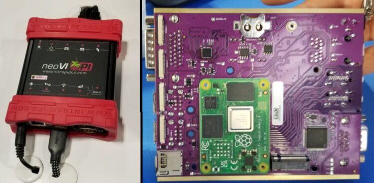
Billed as the Automotive Industry’s first robust platform for the Raspberry Pi the neoVI PI from Intrepid Control Systems (Troy, Mich.) has a built-in Raspberry Pi 4 Compute Module (RPi4 CM) that contains quad 64-bit processors and a gigabit Ethernet port, paired with Intrepid’s CAN FD technology. The point is to provide an inexpensive way to get a Linux connection to vehicle Ethernets. The neoVI Pi has all the features of the RPi4 CM plus up to four CAN FD networks. The neoVI PI is designed for the automotive environment, allowing its use with automotive power ranges. To create the neoVI PI, the company basically designed a circuit board that uses the Raspberry Pi board as a kind of daughter board. The resulting combo board which sits in the neoVI PI is visible at right.
Who doesn’t like roller coasters?
DAQ and controls system maker Dewesoft wanted to illustrate some of the capabilities of its Iolite EtherCAT data acquisition and real-time control system so it set up a Lego-style roller coaster demo that runs under the control of the Iolite system, which also monitors and displays some of the forces on the coaster frame as the cars move around. As explained to us by Dewesoft engineer Dave Gallop, the dual EtherCAT buses on used on the controls are more typically pressed into service for industrial testing applications.
How hot was the show?
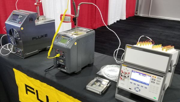
If you’ve ever calibrated a temperature sensor such as a thermocouple, chances are you used a little hand-held meter to do the job. Depending on the RTD or thermocouple involved, you could probably get to accuracies on the order of 1°C down to perhaps a few tenths of a degree. When that level of accuracy just isn’t good enough, you might have to go to something like the Fluke field metrology wells visible here which can hit accuracies of ±0.01°C depending on the temperature measured. The typical job for these instruments is checking out 4.20 mA transmitters. Fluke says traditionally, calibrations of temperature transmitters have taken place on the measurement electronics, while the sensor remained uncalibrated. But typically 75% of the error in the transmitter system is in the sensing element. To make a measurement, the transmitter sensor is placed in the well with a reference platinum resistance thermometer and the transmitter electronics are connected to the front panel of the instrument.
Moving radar targets around manually is so 20th century
The old way of putting automotive radar through its paces was to set the transmitter in an anechoic chamber and move some targets around to see what happened to the echos. Now it’s easier to use something like the Rohde&Schwarz AREG800A radar echo generator. As demonstrated by R&S engineer Scott Niemiec, the generator records the radar signals and plays them back to simulate targets that are moving in specified ways. Basically, you can just turn a dial on the generator to move the targets around. The spectrum analyzer in the demonstration has a bandwidth of over 80 GHz, helpful for seeing radar signals directly with no worries about mixer products as might show up if a mixer was used to down-convert the radar data.
What to know about VNAs and cable tests
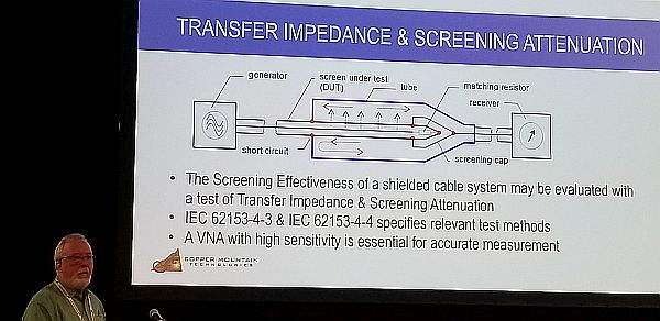
Technology presentations were a big part of the Test expo, including one by Copper Mountain Technologies engineer Brian Walker on how to use a vector network analyzer to evaluate cabling used in high-speed automotive networks. There are some tricks to making the measurement, says Walker, including the use of a special test fixture that holds the cable and prevents external fields from garbling the measurements, and use of some digital pre-emphasis on data signals to improve measurement qualities. And it takes a four-port VNA, rather than a two-port model, to actually run some of the coupling attenuation tests involved.
The biggest 5G phone you’ll ever see
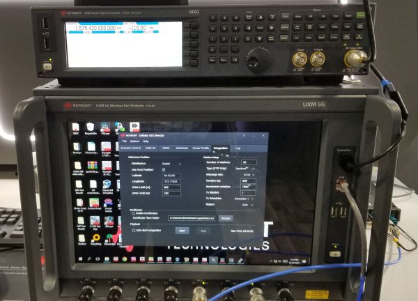
Keysight Technologies demonstrated test gear in several automotive areas including signal simulation. One spot in the Keysight booth featured the E7515B wireless test platform which had been combined with a vector signal generator to produce simulated signals used to wring out automotive wireless connectivity functions. As explained to us by Keysight engineer Shakeel Zafar, the VSG generated GPS signals while the E7515B generated everything else. The E7515B can establish a 5G call with a DUT in different 5G New Radio deployment modes; non-stand-alone, stand-alone, and frequency bands FR1 and FR2. The device performs signaling tests for device RF characteristics, protocol compliance, and functional key performance indicators. It also supports LTE, eMTC and C-V2X signaling formats.




Leave a Reply
You must be logged in to post a comment.