Analog Dialogue is a free technical magazine from chip makers Analog Devices Inc. Published monthly since 1967 and now done online, Analog Dialogue covers circuits, systems, and software for signal processing that relate to ADI chips.
A feature in Analog Dialogue recently caught our eye because it covered some interesting territory relating to the generation of sine waves from triangle waves using a differential pair of transistors. Specifically, the authors start out saying:
We know that the transconductance of a differential pair of transistors is defined as:
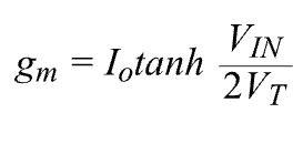
Where IO is the differential pair tail current, VIN is the differential input voltage, and VT is the thermal voltage, which is about 26 mV at room temperature.
The statement is correct but may come as news to engineers who learned about transistor operation via the classic hybrid-pi or Ebers-Moll model in that there is no mention of hyperbolic functions in either one. So a brief review of the relationship’s origin might be worthwhile.
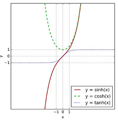 Most engineers probably don’t encounter hyperbolic functions too often, so here’s a simple overview: Hyperbolic functions are analogs of the ordinary trig functions but are defined using the hyperbola rather than the circle. Just as the points (cos t, sin t) form a circle with a unit radius, the points (cosh t, sinh t) form the right half of the unit hyperbola. Similarly, just as tangent = sine/cosine, tanh = sinh/cosh.
What you need to know for the equation to make sense is that an ordinary bipolar differential pair has tanh for a transfer function, basically the difference of the two collector currents. The usual way of extracting this transfer function is via an integrated transconductance amplifier.
We won’t provide the full derivation of the differential transfer function here, but a good discussion of it can be found in numerous places, including a paper from the 2009 6th International Multi-Conference on Systems, Signals and Devices.
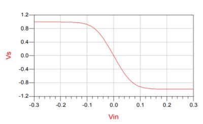
ADI’s approach in its Analog Dialogue article is to feed a triangle wave to the differential pair, then take the output from the two collectors. The two collector signals go to an op amp, an ADI OP27 in this case. ADI suggests looking at the op amp’s sine wave output on a scope FFT display while tweaking the current through the two differential pair transistors, looking for the minimum even-order distortion. ADI also says adjusting the amplitude and dc offset of the input triangle wave can improve the odd-order harmonics in the output.
The output voltage of ADI’s sine wave is approximately
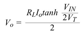
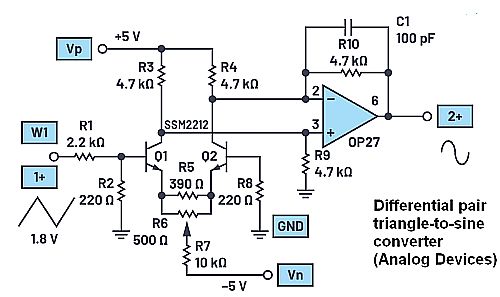
This is basically the differential pair transconductance multiplied by RL/2. Here RL represents the 4.7 kΩ resistors on the output. The division by two happens because the output circuit is only single-ended, not a differential output.
At this point the ADI authors employ a neat mathematical explanation to show the feasibility of getting a sine wave from a triangle wave. The explanation involves a Taylor expansion. Recall that a Taylor expansion (or series) of a function is an infinite sum of terms made up of the function’s derivatives at a single point:
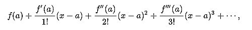
where f(n)(a) denotes the nth derivative of f evaluated at the point a. Taking the first few terms of the Taylor series (that is, the partial sums) of the sine and hyperbolic tangent functions gives this:
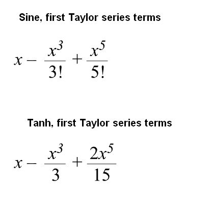
ADI then says that comparing the two Taylor series shows they both have first-order linearity. The term “first order” in this context means that the first derivative appears. What they are actually saying is that the first two terms in the Taylor expansion for the sine and triangle wave–that is, x and its first derivative–are the same.
The interpretation of this result is that applying a triangle wave to a differential pair with a hyperbolic tangent transfer function while keeping the amplitude low—that is, on the order of 2VT—should produce an output nearly indistinguishable from a sine wave. The purpose of the 2.2 kΩ and 220 Ω resistors at the input of the differential pair (base of Q1) is to attenuate the triangle wave signal from the AWG to operate the circuit in the range where the output is as low a distortion sine wave as possible.
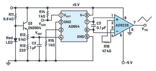
ADI also gives a circuit for generating a triangle wave for those who prefer that method to just hooking up an AWG. The basis of it is an AD654 voltage-to-frequency converter chip used in a slightly unconventional way. The normal output of the AD654 is an open-collector digital square wave. But the triangle wave generator actually uses the internal timing circuit of the AD654, which is a ramp generator. The internal ramp waveform is available on two pins but won’t stand much of a load without distorting. So an AD8226 instrumentation amplifier serves as a buffer and converts the differential signal to a single-ended signal. Tweaking the amplitude of this triangle wave signal allows use of the triangle wave in the sine wave-converter circuit


The Sin(x) expands into x-x^3/6+x^5/120 (if you expand factorial) which is not the same as x-x^3/3+x^5/7.5.
So the statement from Analog devices is not pursuading. The signal will look visually “like” a sinewave, but it will have more 3rd and higher order harmonics.
And the conclusion that it will be a good converter because it has linear term (?) is not intuitive, the real matter is what coefficients it has with higher order terms.
In that past, the usual methods to create more or less accurate sinewaves were using by the non-linearities of diodes and FETs (see the pictures below), analog multipliers which created x*x^2 term with multiplier ICs, and (probably best) using piecewise linear approximation.
It actually depends what is the use of the output. If it is to drive AC motor or actuator, then it will be fine. If it is to measure frequency response or THD of a HiFi amplifier, it is not…
And now it is replaced by digital arbitrary function generators where the waveform is stored in the ROM table…
Dmitrii.