It pays to know the difficulties that can arise when testing and evaluating ground systems for solar panel arrays and wind farms.
Jeff Jowett, Megger
Industrial wind turbines are typically 280 ft high and getting taller. Their height makes them prime targets for lightning strokes that peak in less than 10 µsec while producing tens of thousands of amperes at one-million volts. A lightning strike can cause expensive damage or force a total replacement of the structure. Estimates are that up to 80% of wind turbine damage is caused by lightning. Yet adequate protection runs only about 1% of the total cost of a new turbine.
 Lightning strike density varies enormously across the U.S. Much of the far west experiences less than only one stroke per year per square kilometer. Florida is the most hard-hit area and averages 32.2/yr/km2. The U.S. wind farm industry is now expanding into lightning-prone environments that may call for more extensive protective measures. A thorough protection design must consider not only the exposed blades but also the nacelle, structure, high-voltage power system, low-voltage control, and drive train.
During a lightning strike, blades can experience temperature rising to 30,000° C, causing delamination, melting, surface damage, and cracking along their edges. Much of this damage can go undetected but will shorten the blade life. Switchgear, frequency converters and transformer stations are also vulnerable. Sensors, actuators and steering motors in the control system can be damaged, and batteries can even explode. Lightning damage in the control system is the most common result of a strike while blade damage is most expensive. The single best protection against all such damage is a low-impedance path to earth. Surge protection devices will fail if ground resistance is high.
Towers in wind farms are typically daisy-chained or connected in a star configuration, making the grounding system potentially enormous and complicating the testing requirements. Phase cables have grounding sheaths connected to common buses. Communication cables have their own grounded conductors.
As farms grow larger, it can become impossible to isolate the ground of a single turbine. If a field is under construction, it is a good idea to test the grounding of individual turbines before they become interconnected, as the distances involved in testing the entire completed field as a unit may be prohibitive. Also, lightning protection invokes a different set of criteria than power grounding because of the enormous currents and high frequencies of lightning strokes. Fault clearance and lightning protection have different criteria and may even be cross-connected inadvertently. Fault-protection grounding tends to be shallow buried. The current need only seek its source, typically a similarly grounded transformer. In contrast, safe dissipation of a lightning stroke’s enormous energy involves much greater depths.
Another point to note: Sometimes wind turbine installers take shortcuts. For example, they may have grounded the tower to a nearby power conductor. The mere physical act of stretching test leads to extreme distances can be daunting. Testing may not be difficult for only one turbine. But a good practice is to keep precise records of exactly where test probes are placed to provide a frame of reference for subsequent tests as the power grid expands.
Testing often becomes inadequate and unrepeatable as turbine sites expand. But exact records of test probe locations and maintenance tests over years can still be useful for comparative purposes, even if prohibitive distances to “remote earth” make it impractical to get true resistance readings.
It is beyond the scope of this article to cover the complicated phenomenon of ground coupling, but it is a good idea to become familiar with it. There is a great deal of metal in the ground at a wind farm. Thus it is easy for the lightning ground to couple with a nearby grounded cable. The coupling provides a low-resistance path that shorts out test current and prevents it from evenly distributing throughout the soil. Consequently, ground testing is inaccurate.
Though not as dramatically exposed as wind turbines, solar paneling is often a lightning casualty as well. Rooftop solar structures have the same height problem as tower blades when it comes to lightning susceptibility, though not to the same degree. And ground mounts on solar farms may be the only raised structures for acres.
There is a high-frequency impedance between the grid frame and grounding electrode such that the rate-of-rise of the impulse is much higher than it would be at dc. In the absence of surge protection, lightning energy will enter the dc side of the system and couple into the ac side at the inverters, destroying much in its path.
If panels reside on a building, lightning energy enters the house wiring and connected devices. Home surge protection power strips often lack the capacity to deal with so much energy and are generally only effective against much lower voltages and currents. The grounding conductors at the panels can develop significant voltage against the grounding electrode.
Another point to note: Adding a separate grounding electrode for the solar panel frames can only make the situation worse. In this case, there is no longer an equipotential ground. Rather, the building electrical system may develop a high voltage compared to line or neutral conductors.
Proper grounding and bonding is essential. NFPA 780 specifies requirements that can minimize damage to a PV system and attendant structures. National Electric Code Articles 250 and 690 specify compliant wire sizes, materials and techniques. Underwriters Laboratories, in UL 96A, specifies lightning protection components including size, location and installation.
For safety, all electrically conductive components should be maintained at ground potential. With the frames and mounting structures of a solar array, this is a lot of equipment. Any extraneous current, as from a lightning strike, is provided with a low impedance path-to-ground that effectively shunts it around personnel while activating protective devices.
The NEC states that exposed non-current-carrying metal parts of module frames, equipment, and conductor enclosures shall be grounded. The equipment-grounding conductor runs alongside other conductors in the array and combines components like inverters, disconnects, combiner boxes, battery boxes and any metallic-box-holding electrical equipment. The system must have a properly sized conductor connected to the ground lug and to the grounding system. Every module must be connected to an equipment grounding conductor (EGC). There is frequently a connection point residing at about the middle of the long edge of the frame.
The EGC must be sized properly. The requirements are set forth in the NEC based on the overcurrent protective device (OCPD). A ground fault protection device should also be installed. Not all PV systems require an OCPD. In such cases, the grounding conductor can be sized based on the short-circuit current. No gauge smaller than 14 AWG should ever be used. Installation in conduit can be useful as protection from the environment, corrosives and vermin.
The EGC will be ineffective if not terminated in a grounding electrode (ground rod) of low resistance. Different organizations set their own standards, but generally, a ground of 5Ω or less should be installed. Deep-driven rods may be the most effective but can also be expensive. Instead, a buried grid or array of interconnected rods can suffice. Rods should always be placed farther apart than they are deep, so their fields don’t coalesce and act as one. Roof mounts can use the steel reinforcement in the concrete foundation (generally called a Ufer ground). However, it is a good idea to have a supplementary rod as fault clearance can damage the foundation.
A remaining element is the grounding electrode conductor (GEC). It goes from the electrode to a point where all other grounded conductors can be connected. This point is commonly the ground busbar inside the main distribution panel. If the PV system is utility-interactive, the grounding is then paralleled with the existing utility system ground. This practice prevents development of a voltage gradient between them that will behave counter to the purpose of the grounding system.
One method is to connect an additional ground rod at the inverter and parallel it to the existing utility electrode. The inverter ground rod must have the same gauge as the utility GEC. Another method is to run a GEC from the inverter to the existing utility electrode, sized according to NEC.
Standalone, battery-based systems where the solar array represents the sole power source to the ac load require a new grounding electrode. Here two 6 AWG or 4 AWG GECs are connected, one from the dc wiring enclosure where the inverter connects to the battery bank, the other from the ac MDP (main distribution panel). The NEC recommends separate GEC sizes for ac and dc sides. In stand-alone systems, the grounding electrode is installed as close to the MDP as possible. Without conduit, 6 AWG is the recommended size for the GEC which should be robust enough for physical protection. If the GEC is not exposed to physical damage, 8 AWG on the dc side is sufficient.
The minimization of lightning damage depends fundamentally on just two common factors: bonding and grounding. Bonding provides a low-impedance path via a grounding conductor from the point of lightning contact to the earth, where the grounding electrode facilitates transfer into the soil. In wind power facilities, tests of bonding effectiveness are electrically simple but physically difficult. Tests typically use a low-resistance ohmmeter having a four-terminal Kelvin bridge to establish a test current from 1 to 10 A through the grounding conductor and measure the total resistance with micro-ohm accuracy. A mere continuity test is insufficient because it only establishes that an electrical path exists, not that it is adequate. For wind towers, the difficult part is the long distances involved. But special leads can mitigate the distance problem while the bridge configuration automatically eliminates lead and contact resistance.
The layout of huge solar arrays can make such tests daunting. But a low-resistance ohmmeter is still the correct tool. There may be many parallel paths around the interconnected panels, and these will affect the measurements. So the operator must focus on the direct path between the probes while allowing for other, circuitous routes.
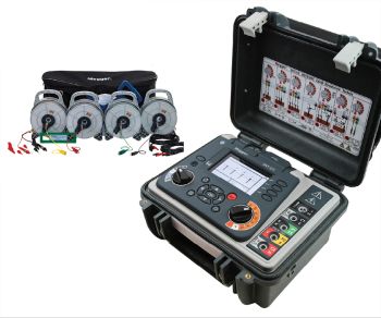
Finally, the grounding electrode resistance must be minimized. This can be a tough job in poorly conductive soils, but the more metal in the earth, the lower the resistance. A dedicated three- or four-terminal ground-resistance tester with a square wave output is necessary, not an ohmmeter. Here procedure is all-important.
Merely stretching out leads and driving in probes will provide a correct measurement only by pure luck. The operator must understand the step-by-step procedure. Fall of Potential is the most accurate and reliable technique, but can experience problems related to distance and labor intensity. An astute operator should be familiar with various test procedures and know the best conditions for applying each one. And this is true for both wind and solar maintenance.
References
Bruce Thatcher, Grounding: The Key To Lightning Protection, Wind Systems
Vaisala National Lightning Detection Network
Richard P. Bingham, Flash, Then Bang; When Lighting Strikes, Electrical Contractor


Leave a Reply
You must be logged in to post a comment.