People these days have had to become savvy about who sent the email in their inbox because of the numerous phishing scams. Thus authentication of email is serious business. For similar reasons, there is much interest in verifying both the source of laser-printed documents and whether a given printed document is the original or a copy.
Many techniques for printer verification use techniques that are analogous to those used for determining the identity of the specific typewriter that produced a printed page: Minor mechanical imperfections unique to a given machine produce artifacts on a page that can be used as a fingerprint for the printer. And it is possible to influence the laser-printing process in subtle ways that embed almost-imperceptible information in a laser-printed document which can serve as a watermark identifying it as an original rather than a copy. In addition, researchers are employing sophisticated methods such as analysis of the “noise” in color printing to ID specific laser printers.
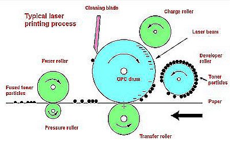 The laser (or electrophotographic) printing process has six steps. The first step is to uniformly charge an optical photoconducting (OPC) drum. Next a laser scans the drum and discharges specific locations on it corresponding to places on the page containing printed information. This is the exposure step. The discharged locations on the drum attract toner particles from a developer roll. The particles are then attracted to the paper, which has an opposite charge, as it rolls past the OPC. Next the paper containing the toner particles passes through a fuser and pressure roller which melts and permanently affixes the toner to the paper. Finally, a blade or brush cleans any excess toner from the OPC drum.
There are minor electromechanical imperfections in any sort of EP printing process. Typical imperfections include fluctuations in the angular velocity of the OPC drum, gear eccentricity, gear backlash, and wobbles in a polygon-shaped mirror which scans the laser beam across the OPC drum. The imperfections create artifacts in the printed output that are directly related to the electromechanical properties of the specific printer. These printed artifacts can be treated as an intrinsic signature of the printer.
The most visible print quality defect in the EP process is banding. It takes the form of cyclic light and dark bands
most visible in midtone regions of the document. Banding is undesirable in printed documents, so there has been a lot of work on banding reduction techniques. The typical approach is to adjust the laser intensity/timing/pulse width, motor control, and laser beam steering to adjust certain process parameters on the fly.
When perfecting ways of watermarking a laser-printed document, it is desirable to work with signals having a high spatial frequencies because humans have trouble detecting them. Problem is, several of the components in the EP printing process don’t have the bandwidth necessary to create the necessary toner bands. For example, motor control loops have difficulty producing high spatial frequencies because of relatively slow loop bandwidth. However, laser intensity can be modulated far faster. So researchers can use laser modulation as a means of injecting an artificial banding signal into the document that serves as a watermark.
For example, researchers at Purdue University used a laser intensity modulation scheme which allowed them to change the intensity of the laser for every new scanline. The scheme let them embed two bits in every three lines of text. For a 12-point document this means about 33 bits embedded in every page of text.
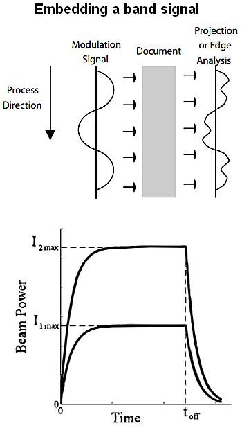
They use the intensity changes for embedding in the toner a set of square waves at various frequencies and amplitudes that lie below the human visual sensitivity threshold curve. Fourier analysis can then detect the signals. Because the printed area comprising a text character is saturated with toner, any slight variation in exposure has no effect. But turning the laser on and off under different exposure settings causes artifacts on the edges of the text characters which can be detected.
Purdue researchers treat each line of text in a document as a signaling period during which one of three symbols is transmitted, basically 1, 0, and null (no laser modulation). Square wave modulation is used instead of a sinusoidal to escape dot size instability. On the edge of a text character dots will be so close together that electrostatic forces may cause interactions between the toner particles making up the dots. This interaction can affect the dot sizes before the toner is fixed to the paper in the fusing step.
The frequencies practical for use in creating symbols are bounded by variables related to the document being printed, the printer, and the scanner used for detection. The font size of the document imparts a lower bound on the usable frequency range. Because researchers want to detect signals from the edges of both upper and lowercase characters, the lowest usable frequency must be such that at least one cycle is present in each character. The embedding frequency is also upper bounded by the combined modulation transfer function of the printer and scanner.
To extract and decode the embedded signals, the document is scanned and individual lines of text are then extracted and processed individually to determine what character contains what symbol.
If the aim is to simply identify the EP printer making a given document, rather than to watermark the document, the geometric distortions the printer puts in printed characters are enough to make an identification. Researchers at the University of Rochester computed what they call a geometric distortion signature from test images and to printer signatures they had in the database.
Before physical printing, most laser printers use halftoning algorithms to binarize the continuous tone image where each color at any point in the image is reproduced as a single tone. The resulting halftone image gives the same visual perception as a solid image from a typical viewing distance. EP printers typically produce halftones via what’s called clustered-dots. Clustered-dot halftones produce gray levels by modulating the size of dots, keeping their distances fixed on a regular lattice. The UofR researchers used this fact to record small local variations in dot positions on a printed page. These formed a geometric signature that could be compared to estimated dot positions before printing. The result was a distortion signature unique to each EP printer.
The above techniques seem to work well for monochrome laser printing. Researchers in Korea have devised a different method specifically for color EP printers. Their approach is to gauge the noise in printed images as a means of forming a fingerprint unique to a given machine. So far, they’ve been able to discern the specific printer manufacturers and specific model numbers of machines producing the images they’ve checked. They say it will take more work to narrow color images down to one specific printer.
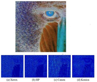
The Korean color laser printer identification scheme basically uses machine learning. To train the model, researchers extracted 60 statistical features from printed images for each color laser printer which were used to train the model. In testing, 60 statistical features are extracted from each unknown printed image and input to the model for identifying the printing device.
The researchers organize the data to take the form of a gray level co-occurrence matrix. A co-occurrence matrix or co-occurrence distribution is a matrix that is defined over an image to be the distribution of co-occurring pixel values at a given offset. It is used as an approach to texture analysis. The researchers extract five statistical features from the co-occurrence matrices: homogeneity, contrast, energy, correlation and covariance. These features are extracted for each of the cyan, magenta, and yellow (CMY) colors the printer produces in four directions for a total 60 statistical features.





Leave a Reply
You must be logged in to post a comment.