The flat display screens of today typically look great. But when it comes to quantifying their output, confusion may reign. There are three main measurement tools used to gauge the output of displays. Before we get into their details, it might be helpful to review the main display technologies we are typically trying to measure.
The LCD (liquid crystal display) technology used in most of the screens found in today’s laptop and desktop computers consists of a bright LED array behind the flat-screen assembly, providing a uniform light through the display. (Liquid crystal appears to be a misnomer because crystals are thought to be brittle solids with smooth facets as in a cut diamond). Notwithstanding, liquid crystals form the moving display. Light passes through it in either of two directions depending on the polarity of the applied voltage. Thus, as the signal fluctuates, the two polarizing fields alternately transmit and block the LED backlight, forming the image in the flatscreen.
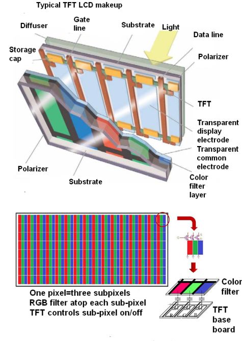
First Leaving the LED array, light passes though a polarizing filter, imparting to it a static polarization, which in the liquid crystal interacts with the fluctuating polarization to create the signal as broadcast.
The LCD screen uses a thin layer of liquid crystal placed between the two substrates containing transparent electrodes. By generating an electric field between the electrodes, separate pixels or groups of pixels are activated, creating changes in their polarizing behavior. This is what makes the video image that the viewer sees on the screen. Color is added when filters are applied to the individual pixels.
An interesting improved viewer experience involves the intentional disabling of all or parts of the LED backlight when black background is desired. This explains the deep blacks seen in upscale TVs. It is an aesthetic improvement over the gray backgrounds in earlier displays, and there are the added benefits of energy savings and heat reduction.
Highly efficient LCD screens have more or less obsoleted plasma TV displays consisting of two glass plates separated by thin neon-filled gaps. The plates have parallel sets of electrodes set at right angles to one another. Voltage applied between the electrodes causes segments of the gas to glow. This illumination is sustained by a lower voltage applied to all electrodes. Because the light is created by the glowing gas, there’s no need for a backlight.
That brings us to the organic light-emitting diode (OLED) display in which an emissive electroluminescent layer contains a film of organic compound that emits light in response to an applied electric current. Each OLED pixel produces its own light, so OLED screens have superior contrast. Because OLED screens have no backlight they can be much smaller, flexible and lighter than an LCD. LCDs are generally 10 times thicker than OLEDs, which have a thickness of around 0.2 to 0.3 mm. OLED displays also use less power than comparable LCD screens. That makes OLEDs a favorite for portable devices like smartphones. And OLEDs refresh up to 200 times faster LCDs so do better at displaying sports or other fast-moving images. They also offer a large viewing angle and display truer colors when compared to LCDs. However, OLED screens don’t last as long as LCDs–The organic molecules degrade with time. Additionally, organic molecules are water sensitive, an issue for devices facing humidity or challenging environments.
The simplest measurement instrument for light levels is the photometer. The old light meters used with film cameras were basically photometers. These generally use a photodiode or photoresistor as a sensor which provides a reading of the amount of lumens the sensor sees. Filters and other options can be added to make the photometer sensitive only to specific light wavelengths, but the read-out always corresponds to the amount of light hitting the photometer sensor.

Displays are characterized by more than just their light output. The more typical measurement concerns the relative values of the displayed colors and whether they are such that displayed images correspond to the colors that the original image contains. The instrument that gives this kind of information is a colorimeter or, more properly, a Tristimulus colorimeter. It is basically a photometer combined with color filters. It takes a limited number of spectral energy readings along the visible spectrum via its filtered photodetectors and outputs adjustment factors for circuits handling the color rendition.
Getting a true color display is a big deal among professionals in graphic arts, so there are colorimeters designed specifically to handle displays found in laptops, desktops, mobile devices, and projectors. Most of these go for a few hundred dollars or more. The usual approach employs software downloaded to the target machine that generates color-patch test patterns on the display. The colorimeter, after allowing for the level of ambient room lighting, is set on the display and notes what it sees in the color patches. Then the software provides a chart of RGB gains and screen brightness. The user at this point goes to the display settings to adjust RGB gains and brightness to line up with the generated chart. Then the colorimeter goes about creating what’s called a gamma profile for the screen. This is basically the amount of luminance coming from each pixel at every brightness level, from 0-100%. Once the profile has been generated, the user generally just clicks on a button to install it on the monitor.
A colorimeter is basically a limited version of an instrument called a spectrometer. The colorimeter is optimized for collecting only the wavelengths of visible light that a display generates. In contrast, a spectrometer collects information about a material based on the amount of infrared, visible, or ultraviolet light it projects. There are several different kinds of spectrometers. Absorption spectroscopy measures the amount of light absorbed with respect to the wavelength. Infrared Spectroscopy measures the vibrations of the interatomic bonds of a sample when the sample sees infrared light. With X-ray spectroscopy, the inner electrons of sample molecules are excited and then fall into the vacancy generated as a result of energy absorption to produce an x-ray fluorescence emission spectrum. In the same vein, UV and laser spectroscopy generate specific emissions from the samples reacting to those kinds of light rays.
Finally, there is a difference between a spectrometer and a spectrophotometer. To make things a bit confusing, spectrophotometers incorporate a spectrometer. The spectrometer is the part of the instrument that measures things. But the spectrophotometer is a complete system that includes a light source along with a means to collect the light that has interacted with the substances being tested, as well as a spectrometer for making measurements. Spectrophotometers measure the way solutions absorb wavelengths and reflect them, as well as the transparency or transmittance of solids.


Leave a Reply
You must be logged in to post a comment.