Hysteresis might be defined as something that happens when the physical state depends upon its history. The classic example of hysteresis in action is the residential thermostat. It has built-in hysteresis to prevent rapid cycling. It’s low cut-in and high cut-out levels are designed to prevent the heating/cooling system from rapid switching, which would quickly damage and ultimately destroy controllers and loads.
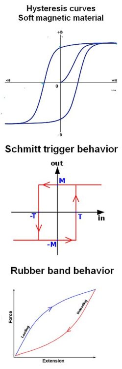
In many examples of hysteresis, plots of behavior form a loop or hysteresis curve where one variable has a different value depending on the direction of change of another. One example of such behavior can be found in soft magnetic materials; this history dependence is the basis of memory in hard disk drives.
Hysteresis behavior is often divided into two categories, simple hysteresis (or rate-independent hysteresis) and rate-dependent hysteresis. Systems exhibiting rate-independent hysteresis have a persistent memory of the past that remains after the transients have died out. Magnetic hysteresis loops in soft magnetic material are rate-independent. In contrast, rate-dependent hysteresis implies a dynamic lag between an input and output. If the input goes to zero, the output continues to respond for a finite time. Thus the memory of the past is limited because it disappears as the output decays to zero. The phase lag depends on the frequency of the input and goes to zero as the frequency drops. An example of rate-dependent hysteresis is that due to dissipative effects like friction.
Contact bounce in switches and noise in electrical signals can be mitigated by
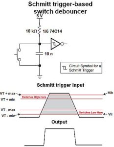
intentionally adding hysteresis. An example is the Schmitt trigger, a comparator circuit in which hysteresis is implemented by applying positive feedback to the non-inverting input. The output retains its value until the input changes enough the trigger a change in the output. The Schmitt trigger is said to possess memory, enabling it to function as a bi-stable multi-vibrator, also known as a latch or flip-flop. Other applications are computer memories, relaxation oscillators, function generators and switching power supplies.
Gear lash illustrates mechanical hysteresis in machine components. A small gap between meshing gears permits lost motion (play)–if rotation of the drive gear reverses, the driven gear will not start to move until the drive gear re-establishes contact. Spur gears exhibit the most backlash, planetary gearheads exhibit low backlash, and harmonic gearheads exhibit no backlash.
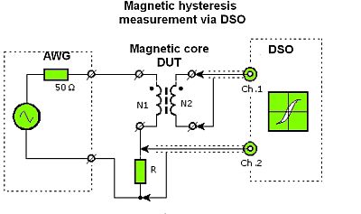
Measurement of hysteresis qualities is usually straightforward. As an example, consider the procedure for measuring the hysteresis of magnetic cores as used in inductors and trasformers. The magnetic hysteresis loop reveals a lot about factors such as the core power losses and the maximum permissible modulation. Moreover, these qualities often aren’t part of the material specifications. They must be determined for individual uses because wave shape, frequency, duty cycle, and other factors all affect them.
To measure core properties, the core must be wound with two windings, a sense and driving winding. Both have the same number of turns, usually the more the better. The first winding is fed with ac at the frequency of interest. Its current I is directly proportional with the field strength H. The second winding measures the resulting voltage E. Induction B can then be calculated.
Measurements of core magnetic induction use the fact that the generated E in the windings is proportional to the flux change dΦ within the core: E=-N(dΦ/dt). The flux density is equal to the product of the magnetic induction and the cross sectional area of the core, Φ = B·Ac. The relationship between the change in induction and E is: ΔB = (Δt·E)/(-N·Ac).Integration of this induction change ΔB allows the calculation of induction as a function of B:
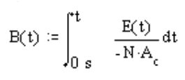
Modern digital scopes typically have math options that include integration which allows the scope itself to do this measurement. Integrating the secondary voltage yields a flux in V-sec (Webers). This is converted to the flux density as B = Φ/(N·Ac)
For displaying the hysteresis curve, the scope is set to the X-Y mode with field strength H plotted on the X axis, flux density B on the Y axis.
Finally, one last hysteretic effect to consider: One of the many unfortunate effects of the current covid-19 plague is a growth in the number of unemployed. Unfortunately, it turns out that structural unemployment is hysteretic. That means at best there will be a significant time lag between the end of Covid-19 and full employment. There are many factors that may conspire to introduce a large hysteresis into the post-pandemic workplace equation. For example, loss of job skills by a significant fraction of unemployed or changes in job descriptions that obsolete previously valuable worker knowledge.
Of course, it is not certain that this gloomy assessment is entirely accurate. Let’s hope the hysteresis curve turns out to be small.

Dear madam/gentlemen,
I just have one question and would like to confer with you in term of Hysteresis compensation and measurement.
Have you ever experimented with Magnetostricitve Actuator, or some sort of Smart material Applied in Actuator to measure hysteresis behavior?
the second question is that, Do you have any method or technique to compensate hysteresis or alternative way to reduce loss coming from hysteresis.
If you have any clue or experience, please feedback to me. I really want to discuss this issue with you, or is this possible to your agency.
Thank you so much!