MIL-STD-1553 was first used by the US Air Force in 1973 to define a serial data bus for military aircraft, notably the F-16 Fighter. It soon began to be a means of moving data in many other US military jets, as well as in domestic and foreign avionics, showing up even in the Russian MIG-35.
MIL-STD-1553 Bus was designed for reliability. Data loss or corruption, of course, can result in an aircraft falling out of the sky. Reliability is implemented in a variety of ways, both in the physical layer (cabling, connectors, etc.) and the way in which information is ordered and conveyed. Both of these differ in comparison to other data bus types.

The cable bus is a pair of conductors having an impedance around 75 Ω at 1 MHz. As in other serial bus data transmission methods, there are transmitters and receivers. They couple into the bus through isolation transformers, which prevent short-circuit disasters at 50,000 ft. above the earth’s surface.
Moreover, an emphasis on redundancy has characterized MIL-STD-1553, both as a concept and in complete multiplex installations in all their diversity. The standard currently figures prominently in the International Space Station and spacecraft of all nations.
Independent wire pairs are commonly used to make the bus dual or triply redundant. In these configurations, all devices connect to all buses. The defining components in MIL-STD-1553 bus controller and multiple remote terminals. In addition are bus monitors which, as their name implies, receive and record bus activity but do not play an active role in actual data transfer.
The bus controller and all connected remote terminals have access to all transmissions. Communication is initiated by the bus controller, never by a terminal device. In the case of terminal device-to-terminal device communication, the transfer is initiated by the bus controller.
MIL-STD-1553 uses the Manchester code to transmit the 16 bits that comprise each word. A digital 1 is conveyed by means of a 0.5-μsec high and a 0.5-μsec low. For conveying 0, this sequence is reversed. In this manner, the bus controller transmits data to the remote terminals. When data is to be conveyed between remote terminals, the bus controller initiates the transmission. Unlike in some types of serial buses, all remote terminals are awake at all times and are privy to all transmissions.
All words are preceded by a 3-μsec sync pulse and followed by an odd parity bit. Accordingly, all words consist of 20 bits, this total including:
- 3-bit sync
- 16-bit payload
- 1-bit parity
Words are always continuous within each message, and messages are separated by at least 4 μsec of silence, although this gap can be larger.
When there is a valid command, remote terminal devices need to respond within 12 μsec. If no response is forthcoming within 14 μsec, the bus controller concludes that the command or message was not received. If the remote terminal does not perform as anticipated by sending status or expected data, or if it sends an error message, the bus controller retries the transmission.
Each MIL-STD-1553 bus has one and only one bus controller, although there may be one or more normally off-line backup units. Its local memory contains a command list that provides the operating agenda. Its most fundamental function is to send signals to its associated remote terminals and also to command them to send signals when required. Additionally, it processes requests sent by the remote terminals. The bus controller also detects and mitigates errors and keeps a history of them in its memory.
As mentioned above, there is only one bus controller associated with each MIL-STD-1553 bus. However, there may be a backup bus controller. The 1553 standard specifies that in the event of bus controller failure, the backup bus controller can take over.
Despite the fact that the bus monitor cannot actually transmit messages or commands over the data bus, it performs important roles in monitoring and recording bus transactions without affecting the bus controller or remote terminals. Those records remain available for analysis down the road. Also, a bus monitor can be placed in communication with a backup controller to facilitate the changeover when and if it becomes necessary.
Remote terminals perform a variety of functions. Without remote terminals, there would be no MIL-STD-1553 bus. Individual remote terminals connect to attached subsystems as well as providing connectivity to a different MIL-STD-1553 bus if it exists. Remote terminals are used, for example, to turn on and off aircraft headlights, landing lights and annunciators.
Of course, the high degree of reliability necessary in MIL-STD-1553 bus systems can be made possible only by a high-functioning hardware system that includes cabling, terminators and connectors in addition to bus controllers, bus monitors and remote terminals.

Serial bus standards typically specify a range of values for cable characteristic impedance. MIL-STD-1553B specifies 70 to 85 Ω. Manufacturers have refined this figure to 78 Ω. Characteristic impedance is not affected by the length of the run because the cable is precisely manufactured so its series inductance and parallel capacitance neutralize one another. However, they work in concert to boost attenuation in proportion to cable length.
Attenuation can be minimized by using thicker wire. But propagation delay, always 1.6 nsec/ft., must be considered, especially when it becomes equal to 50% of the signal rise time in lengthy cables.
When stubs are attached to the main bus, this loading gives rise to potentially harmful transmission line reflections. High stub impedance minimizes reflections but simultaneously reduces signal power at the remote terminal, so system design must address these issues.
The MIL-STD-1553 spec merely states that shielded cabling is required, but twinax is universally used. It resembles coax but with two inner conductors rather than one. It is used for all connections: Bus controller, backup bus controller, bus monitor and all remote terminals. The insulated pairs are balanced and shielded. The twisted construction of the pairs reduces noise and alien crosstalk. The high dielectric constant non-conductive filler material controls capacitive coupling to ground and promotes a uniform twist rate. In avionics applications, a high-temperature rated outer jacket is used.
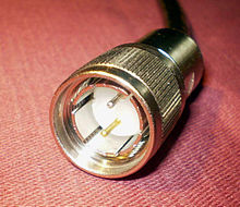
MIL-STD-1553 does not specify connector types and wiring methods. But for military aircraft, general practice calls for MIL-DTL-5015 and MIL-DTL-38999 circular connectors.
To promote and ensure reliability, MIL-STD-1553 precisely specifies terminal operation. Because this is where data from the bus controller is received, processed and applied to on-board actuators, its operating capability has to be maintained without interruption.
A preliminary requirement is word validation. The terminal accordingly ensures that each word as received from the bus controller begins with a sync field that is valid. Within each word, the bits must conform to the applicable Manchester code. In addition to odd parity, the information field is to have 16 bits. Words that do not meet the above standard are labeled invalid.
Transmission continuity must be maintained, i.e. not garbled within the Bus controller, remote terminal or connecting media. Improperly timed sync also impacts accuracy in data transmission.
To protect from faulty operation, remote terminals contain hardware that initiates a time-out when the signal is of a duration greater than 800 μsec. Provisions are in place to override the time-out when correct transmission responds to a command, and reset takes place in response to a verifiable command. Invalid and illegal commands must be in some manner filtered out so they do not lead to improper operation downstream from the Remote Terminal.
Displaying MIL-STD-1553 signals
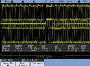
One difficulty working with bus signals stems from the fact that they are differential signals. That means the bus can only be probed with differential probes. Another difficulty arises in triggering scope displays from bus signals. Without special MIL-STD 1553 triggering, it can be tough to set up a scope to synchronize its acquisitions/sweeps on specific MIL-STD 1553 Words or messages. Nor is an external synchronization signal generally available for scope triggering.

Most standard oscilloscopes trigger on some kind of edge crossing. Using this triggering mode on 1533 signals will bring a repetitive overlay of all input and output Words (data, command, and status). To simplify the task of seeing characteristics such as transition times, voltage swing, etc., some scope manufacturers make available special MIL-STD 1553 triggering/decoding packages to let scope users focus on specific input or output words and/or messages for analog characterization.
For example, one such package from Keysight lets scopes trigger on error conditions involving Parity, Sync, and Manchester codes. It also implements a triggering mode called “Remote Terminal Address + 11 Bits.” It lets the scope trigger on specific Command or Status Words to isolate measurements on specific types of Words and message transfers.
To measure the analog qualities of received/input signals, the scope is setup to trigger on either command Words generated from the bus controller,
or to trigger on status Words generated by other remote terminals in the system. The Keysight package lets users specify the contents of the 11 bits that follow the remote terminal addresses to trigger on. Using this field for additional trigger qualification lets the scope trigger on specific transmit or receive command Words, or to trigger on specific status words.

Leave a Reply
You must be logged in to post a comment.