Mask testing is used in production facilities for screening and quality control of components and electronic equipment and also for debugging and troubleshooting. It is quick and efficient and lets users identify harmful anomalous behavior that arises in one or a billion waveforms. It involves setting limits of acceptability on signals at the outputs of devices under test, and detecting when the signals appear outside those limits.
Many digital storage oscilloscopes incorporate mask testing, some as an option that is purchased separately and installed as an application module. The basic idea is to set up an ideal waveform and then define amplitude and temporal (vertical and horizontal) margins of acceptability around it. The oscilloscope will identify and display occurrences where the signal falls outside these margins on a pass or fail basis. Then the instrument will react in a user-defined way.
Oscilloscopes that offer mask testing are configured as demonstrated in a Tektronix MDO3000 instrument:
To demonstrate mask testing, first we’ll display a sine wave from the internal AFG, fed into the Channel One analog input. This waveform should exhibit no violations. Press Default Setup, Autoset and Channel buttons to get a good display. Then press the Test button, which resides on the front panel in the Wave Inspector section. In the horizontal menu that appears at the bottom, press Application and using Multipurpose Knob a, scroll to Limit/Mask Test. The applicable horizontal menu appears at the bottom.
The required operations are in sequence, beginning at the left. Select the first choice by pressing the soft key associated with Set Up Mask, which is currently Off. The vertical submenu shows up at the right. Press the soft key associated with Display Mask, which toggles it On and displays a generic mask for the sine wave, as yet undefined by the user. Now press the soft key associated with the bottom submenu item, which permits the user to verify that Mask is locked to the desired source, in this instance Channel One.
Returning to the Limit/Mask horizontal menu at the bottom, press the soft key associated with the second menu item, Select Mask. The appropriate vertical menu appears at the right so that we can choose between Limit Test and Custom Test.
A custom mask can be created from a test file. For now we’ll do the more common Limit Test, which is the default. Returning to the horizontal menu at the bottom, press the soft key associated with the next menu item, which is Create Limit Mask.
The vertical submenu comes up at the right, and we can choose the source, which may be any of the four analog channels or any of the four reference channels. Analog Channel One, currently On, is highlighted.
The vertical submenu also permits the user to set the horizontal and vertical limits, using Multipurpose Knobs a and b or the number pad. These limits are expressed as millidivisions and whole divisions. After the source and limits are chosen, the test has been set up and you can run it by pressing OK Create Limit Mask.
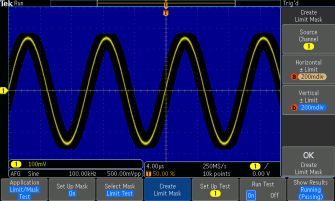
As you can see in the screen shot, the mask as configured in Set Up Test is displayed, surrounding the signal at the input. Because this ideal sine wave remains well inside the amplitude and temoral limits, Results states that the test, which is still running, is passing.
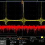
Now, returning to AFG>Output Settings, we’ll add 25% noise. Pressing Test, the results are displayed. (There is no need to reconfigure the test.)
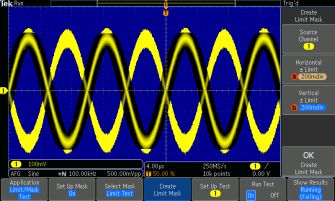
Here the signal goes outside of the mask and results, as shown, indicate that the sine wave, due to added noise, is failing the mask test.
As part of Set Up Test, before reaching the threshold, the number of violations can be set as low as one and as high as 10 million, and then infinity. The test can be stopped after a user-determined number of waveforms or amount of time, ranging from one second to 172,800 seconds and infinity.
Pressing the bottom soft key associated with More, Actions on Failure and Actions on Completion can be chosen. The permitted actions are:
• Stop acquisition
• Save waveform to file,
• Save Screen Image
• Print
• AUX OUT Pulse
• Remote Interface SRQ
Pressing the soft key associated with 3 of 3, a pretest delay, ranging from 10 seconds to 200 seconds can be selected by turning Multipurpose Knob a or entering a value in the number pad. Also, Repeat on Completion can be toggled On or Off.
Beyond passing or failing, detailed Limit/Mask Test Results can be shown.
These consist of:
• Test Status
• Total Waveforms
• Violations
• Total Tests
• Failed Tests
• Elapsed Time
• Total Hits
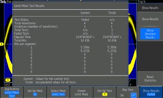
The second menu item in the vertical menu Show Results submenu is Show Detailed Results. To the above numbers, Hits Per Segment is added. The bottom soft key resets statistics to zero in the above windows.
A key concept in quality assurance programs is the six sigma metric. Promulgated by Motorola in the 1980s, six-sigma quality assurance has permeated the test and measurement industry. It consists of holding the number of defects in a product, device, circuit or component to under one in 3.4 per million samples. To meet the standard, out of 294,117 waveforms (1,000,000 divided by 3.4) sampled, all would have to pass on the basis of several parameters that might include frequency, RMS voltage, peak-to-peak voltage and delay.
Performing these separate tests on a million samples to find 294,117 passes (times the number of devices under test) would be time-consuming even with highly automated testing, and this is the thinking underlying mask testing, where compliance can be validated at an (electronic) glance. In addition to a conventional time-domain sine wave as discussed, mask testing can be applied to eye diagrams, which in effect greatly multiply the number of occurences covered in each acquisition.
The precision of mask testing is degraded by vertical noise and jitter. This is because such activity, when it is not inherent in the device under test, produces false negatives that invalidate the entire procedure. Accordingly, it is essential to maintain a low noise floor in the test equipment, including cabling and terminations.
Another thing to think about is waveform update rate in the oscilloscope performing signal integrity tests. A fast waveform update rate enables a digital storage oscilloscope to display random and infrequent glitches and anomalies with increased reliability.
To view a waveform clearly, it is often desirable to change the number of waveforms or the portion of a single waveform that is displayed at a given instant. The user can make this change manually by rotating the timebase control. If the update rate is slow, there will be a long pause before the instrument responds. If this delay is several secods, when a great number of acquisitions is required by the intended application, the cumulative dead time is an impediment to good productivity.
To view one or more waveforms clearly in a display, a fast update rate is required. This makes it possible to detect noise and jitter, prime causes of signal distortion and data corruption. A fast waveform update rate facilitates the capture and display of random or infrequent events that contribute to overall signal loss.
The oscilloscope display is not responsive during the time interval between signal acquisition and the completion of processing the previous signal. A faster update rate means less dead time between successive displays. All oscilloscopes experience these periods of apparent inactivity, but the update rate is decisive in limiting the unresponsive interval.
Dead time rises when digital channels are used, so the capturing of glitches and infrequent anomalies becomes more difficult, especially when deep memory and serial decode are activated. In this regard, a large display is helpful because digital signals require more horizontal and vertical space. This is because they are longer and there are more of them due to the high digital channel count. This is especially applicable in mask testing where the margins of acceptability require added display area.
Mask testing and update rate are important topics in digital storage oscilloscope design and operation. They are relevant when it comes to troubleshooting, debugging and production quality assurance.

Leave a Reply
You must be logged in to post a comment.