Electrolytic capacitors are often used because they deliver relatively large capacitance values in a physically small package. The compact packaging is possible because they use a thin dielectric layer in conjunction with an etching or sintering process that vastly increases the area of the plates and the capacitance associated with them.
Most capacitors have two conductive plates, separated by a dielectric layer. (Rarely, capacitors are constructed with three or more plates, and there is also such a thing as self-capacitance.) Capacitance is an inherent property of a device, electronic equipment or a communications or power distribution system. Capacitance does not normally vary except in a varactor, variable capacitor, or as a consequence of component aging or failure. Specifically, as opposed to capacitive reactance, which is frequency dependent, capacitance is constant without regard to the electrical environment.
Capacitors are manufactured to appropriate tolerances and labeled or color-coded indicating capacitance and working volts. However, it is instructive to look at the equation:
C = εr ε0 A/d
where C is capacitance, in farads; A is the area of overlap of the two plates, in square meters; εr is the dielectric constant of the material between the plates, dimensionless; ε0 is the electric constant, farads/meter; and d is the separation between the plates in meters.
As you can see, the defining metrics are plate area, the separation between plates, and dielectric constant of the material that constitutes the dielectric layer between the plates. This material is not merely an insulator that keeps the plates from shorting out. Beyond that, it maintains the close spacing between plates and it is also the medium holding the electrical charge that is the essence of capacitance.

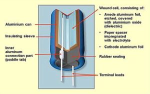
The electrolytic capacitor is more complex than other types. Internal plate and ad hoc dielectric structuring make possible much higher capacitance in a relatively small package. Rather than a simple arrangement of two parallel plates and a dielectric strip wrapped to form a cylinder that is equipped with axial leads, the electrolytic has no dielectric layer until a forming voltage is applied, whereupon it is created in an electrochemical process. This dielectric layer is much thinner than possible using conventional manufacturing techniques, enabling capacitances in the high microfarad range.
Electrolytic capacitors exist in numerous variations, principally aluminum, tantalum and niobium electrolytics. Each of these is available in either solid or non-solid configuration. The non-solid type is used almost exclusively in non-military applications due to its moderate cost.
The common aluminum electrolytic capacitors employ an etched aluminum foil as the anode. The dielectric layer that is formed is aluminum oxide. The purpose of etching is to create a rough surface that has a higher surface area, translating to greater plate area and consequently higher capacitance. Typically, the pathway to greater capacitance in an electrolytic capacitor is two-fold: greater plate area created by sintering or etching and thinner dielectric layer.
The distinguishing quality of tantalum capacitors is their small size and weight coupled with exceptionally high capacitance. Like other electrolytics, the tantalum capacitor is produced by applying a forming voltage to the anode. Solid-electrolyte tantalum capacitors appeared in the 1950s as the transistor was becoming dominant in virtually all electronic equipment. The tantalum capacitor was well suited for these applications because of its small size and high capacitance, but a problem arose when the price of metallic tantalum exploded in 2000. The industry responded by developing the niobium electrolytic capacitor, which used a manganese dioxide electrolyte.
Japan in the 1980s was the scene of an important development in non-solid electrolytic capacitors, the implementation of water-based electrolyte for aluminum electrolytic capacitors. This enhancement permitted a more conductive electrolyte. Unfortunately, substandard pirated devices flooded the market and there were many instances of bursting power-supply capacitors in computers and elsewhere.
Most electrolytic capacitors are polarized devices, meaning that they will not tolerate reverse polarity. The anode voltage must be kept positive with respect to the cathode. Solid tantalum capacitors can withstand a reverse polarization for a short duration but at only a small percentage of the full-rated voltage.
Some electrolytic capacitors are intended for bipolar operation. These capacitors are constructed with two anode plates that are connected in reverse polarity. In successive portions of the ac cycle, one oxide functions as a blocking dielectric. It prevents reverse current from destroying the opposite electrolyte.
One of the special qualities of an electrolytic capacitor is the fact that the electrolyte also serves as the cathode. This electrolyte conforms in an intimate fashion to the roughened face of the anode. It is separated only by the extremely thin dielectric layer, which accounts for the high capacitance in a relatively small package.
It must be emphasized that when working on electronic equipment containing one or more electrolytic capacitors, care must be taken to properly discharge the device(s) before touching any part of the circuitry. That is because electrolytic capacitors often store potentially lethal voltages long after the equipment has been powered down. Shunting out the device with a screwdriver is not a good practice for a variety of reasons, including the fact that the sudden high-current discharge can puncture the dielectric layer, destroying the component.
The preferred method of discharge is to use a low-resistance power resistor equipped with insulated alligator clips. When doing this sort of work, it is a good idea to wear utility workers’ high-voltage gloves (available from Amazon.com for about $40) as additional protection.
Electrolytic capacitors work well when high capacitance and utility-level working volts are required. They often find use in power supply circuits, and when a power supply becomes faulty, it is usually an electrolytic capacitor that is to blame. Fortunately, electrolytic caps are easy to diagnose. Whenever an electrolytic capacitor is seen to be leaking or is bulging, failure is imminent if it has not already happened.
Electrolytic capacitors can fail in one of two main ways, open or short. In an electrolytic that has failed open, the capacitance is reduced to a small value because the electrolyte has dried out. An electrolytic that fails short will blow the power supply fuse if the equipment has one.
Additionally, electrolytic caps are notorious for developing a series resistance over time, especially when operating for extended periods at high temperature. This resistance is dubbed ESR for effective series resistance. It is difficult to test for high ESR using simple equipment. In a power supply high ESR will manifest itself as more ripple though the capacitor will test good using simple equipment.
There are two main ways of testing capacitors: through use of an LCR meter or via a DVM.

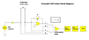
the unknown device and across RrR, respectively are connected to a selector switch. The output of the switch is connected to a differential amplifier. The real and imaginary components of the voltage and current signals are obtained by multiplying
these voltages with a square wave coherent with the stimulus (in the phase detector). This gives an output proportional to
the in-phase or quadrature component, of the voltage. The output goes to a dual-slope A/D converter that the MCU reads. The complex ratio of voltage to current is equal to the complex
impedance. Other parameters such as L and C are derived mathematically from the corrected impedance
value.
The LCR meter applies a sine wave excitation of some selectable frequency to the capacitor, then measures the voltage across the capacitor and the current through it. From these, the capacitance can be calculated. Benchtop LCR meters may have special settings such as for dc bias voltage, dc bias current, and the ability to sweep the frequency at which measurements take place. Electrolytic caps need to be tested at the frequency they’ll see in the end application. That is because their capacitance varies somewhat with frequency. Common LCR measurement frequencies are 50/60 Hz, 120 Hz, 1 kHz, 100 kHz and 1 MHz. Most LCR meters today use an ac test signal over a frequency range of 10 Hz to 2MHz.
LCR meters can also be set to apply different signal levels to the cap under test. This is useful because electrolytic capacitors should be tested at the voltage they will see in actual use. In that electrolytics often find use in power supply circuits, applied voltages can be on the order of hundreds of volts.
DVMs can be used to test electrolytic caps if an LCR meter isn’t available. Some DMs have a setting for capacitance measurements. When in the capacitance measurement setting, the DVM uses the concept of the RC time constant to measure capacitance. The meter applies a known current through a known resistance to the capacitor and measures how long the voltage across the capacitor takes to ramp up. The meter then solves for C from the time constant relationship.
However, a point to note is that the DVM capacitance measurement takes place at one frequency which is not necessarily the frequency at which the cap will see service. And a DVM capacitance measurement won’t take place at the relatively high voltages that electrolytic caps normally see.
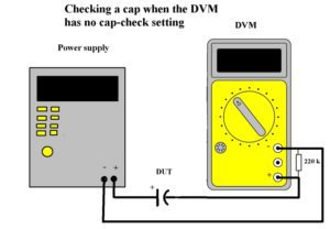
It is also possible to test electrolytic caps with a DVM that lacks a capacitance measurement setting. This procedure uses the same RC time constant calculation for figuring capacitance as is used in meters containing a capacitance setting. The difference is that the operator makes the measurement and does the calculation manually.
One benefit to manually testing caps this way is that the measurement can be set up to take place at a high voltage that the cap will see in real life. But be careful: High-voltage tests put the operator in the vicinity of a high-voltage power supply and its output terminals. So caution is necessary.
The input resistance of DVM is generally in the 10 MΩ range. It’s best to use an adjustable power supply for testing caps. If it is set to 400 V the DVM would be set to the 500-V range. (Recall that the resistance of a DVM changes depending on the setting of the range switch. The meter should always be set to a range higher than the voltage of the power supply so if the capacitor is a dead short the meter will be undamaged.)
 The capacitor under test is connected from the positive power supply output to the positive terminal of the DVM (obey the polarity markings on the cap). The negative terminals of the supply and DVM connect directly to each other. Next connect a 220 kΩ 2-W resistor in parallel with the meter with the meter set to the proper range as explained above. Turn on the power supply. The meter will show a high voltage for a short time but the reading will decay to zero quickly.
The time back to zero is about eight time constants. One time constant in seconds is equal to R in ohms times C in farads. If you are using a meter with 10 MΩ input resistance and you are testing a 0.1 μF cap, the time constant is one second. If the capacitor is good the meter should indicate zero after eight seconds.
If you are testing an electrolytic capacitor calculate the time constant from 220 kΩ times the capacitance in farads.
If the cap is totally shorted the meter will read the output voltage of the power supply and stay there. A more likely outcome is that the cap is leaky. In that case, the meter will spike high and fall back but not all the way to zero. Using a 10 MΩ meter the leakage current in microamps is given by I = V/10.
If the meter fails to spike high it means either the capacitor is open or the capacitance is too small to produce a noticeable spike. Caps ranging from 0.01 to 0.0025 μF are about the smallest that will give the spike depending on the response speed of the meter.
If this testing regime makes the capacitor feel a little warm, it’s warm on the outside and hot on the inside. The heat comes from capacitor leakage current. If leakage current is sufficient to heat the capacitor under these circumstances, the cap is likely bad. It’s best not to use a capacitor with this amount of leakage.
Huge non-polarized metal film aluminum electrolytic capacitors are used for power factor correction when current lags voltage due to a proliferation of non-linear loads. Because loads are routinely switched on and off as needed, frequently the power factor is subject to change. This is especially true in a large facility where numerous powerful non-synchronous motors, lots of powerful fluorescent lighting and copious data processing are present. This is the rationale for automatic power factor correction. It consists of a bank of capacitors that can be individually switched by means of contactors. A regulator monitors both power factor and total connected load and places capacitors on line as required to keep the power factor above a predetermined level.
Another application for electrolytic capacitors is as input and output smoothing if the waveform of interest is a strong dc signal with a weak ac component. But it must be emphasized that some electrolytic capacitors are not suitable in high-frequency circuits because of the power dissipated at the parasitic internal resistance known as equivalent series resistance (ESR).
Electrolytic capacitors are also extensively used as filters in high-end audio equipment to reduce 60-cycle hum from the utility supply.
An interesting characteristic of electrolytic capacitors is that they may have a limited shelf life, often just several months. If left out of circuit, the oxide layer deteriorates. The good news is that it can be rejuvenated by applying to the capacitor a steady, slowly increasing dc voltage.

Leave a Reply
You must be logged in to post a comment.