A comparator, as its name suggests, compares two voltages or currents and determines which is higher. The usual implementation is with two inputs for the voltages that are to be compared and a single output that by mean of a logic high or logic low state indicates the higher of the two inputs.
Typically, a comparator looks at a variable voltage in comparison to a stable reference. In many devices, the reference voltage is integrated onto the chip. ICs are also available with a range of reference voltages.
Comparators may be continuous or clocked. A continuous comparator reads the inputs and reports the results in real time. When the input status changes, the output updates more or less instantly. (In many applications speed is of the essence.) Clocked (also called latched or dynamic) comparators are used when outputs are required only at discrete time intervals, as in analog/digital converters (ADCs). The advantage in this arrangement is that power requirement is lower and accuracy is higher.
.
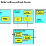
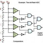
Comparators are widely used in numerous applications. In ADCs, a comparator functions as a digitizer when it ascertains whether a voltage at the input is above or below a predetermined threshold. This operation in conjunction with other devices performs multi-bit quantization as in a digital sampling oscilloscope. Relaxation oscillators use both positive feedback with a Schmidt trigger configuration and negative feedback contributed by an RC circuit so the comparator becomes an astable multivibrator and thus a viable oscillator. Zero-crossing detectors use a comparator to detect when an ac pulse changes polarity, so the comparator outputs a square wave. In null detectors, the comparator identifies the point in time when an input is zero volts.
Just like a residential furnace or hot water heater, a comparator circuit must incorporate hysteresis to prevent uncontrolled cycling at transitions. This is because of small voltage fluctuations caused by noise at the inputs, within the device, and imposed by loading variations. Rather than one transition, there are two, one for rising voltages and one for falling voltages. Contemporary comparators have a built-in hysteresis in the low-millivolt range. If the internal hysteresis is not present or is too low for the intended application, an external hysteresis network can be provided, comprised of positive feedback from the output to the non-inverting input. If hysteresis is added, the comparator will not function within the revised hysteresis band.
If you look at comparator and operational amplifier (op-amp) schematics, you will see that externally, they are equivalent. Both have differential inputs with a single output. So in view of the op-amp’s low cost and flexible packaging, why not use it wherever the more expensive comparator is suggested?
Both devices have inverting and non-inverting inputs and a single output that can go high or low. And both have low offset, high gain, and favorable common-mode rejection. There are, however, some important differences between them, and these determine when an op-amp can and when it cannot be used in a comparator application.
Both devices take note of the inputs in the same way, by ascertaining the relative values, but they form outputs differently.
The logic output of a comparator may be TTL or CMOS-compatible, and this indicates which of the two inputs has a higher voltage level. To do this, the comparator output goes quickly to V+ or V-, in other words, right to one of the rails.
In contrast, the op-amp goes high or low but not necessarily all the way to the power supply voltage. However, the outputs of most op-amps swing fairly close to V+ and V-. Comparators are open-loop systems, able to drive logic circuits, and are fast regardless of whether they are overdriven. In contrast, op-amps are not intended to be overdriven. They are closed-loop systems designed to see only resistive and reactive loads.
Due to their convenience and economy, op-amps have been substituted in certain low-speed applications, but never when high speed is desired.
A comparator’s inputs are analog but the output is fully digital. Because the output drives digital logic directly, it is necessary to constrain it so it is consistent with the digital logic family. (An alternate scenario is that it drives an on-off load such as a mechanical or solid-state switch or perhaps a relatively high-current LED.)
To these ends, the comparator output can be modified with external circuitry. Besides rail-to-rail, some possibilities are floating, open drain, open collector, CMOS logic, TTL logic, CMOS logic with ground pin, and TTL logic with ground pin. The choice has a lot to do with desired speed and power required. The output current is critical unless the comparator must drive digital logic exclusively. For LED and relay applications, high-current MOSFETs and Darlingtons are appropriate.
Input voltages must remain within the operating range, which varies greatly with different components. If the comparator is intended to operate with a low voltage single supply in the 3 to 5-V range, inputs may go to ground or slightly below.
One important input parameter is the input offset voltage. This is the differential input voltage necessary to make the comparator toggle. Often denoted VIO, the input offset voltage limits the comparator resolution.
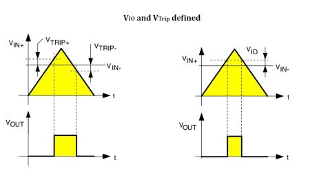
Comparator makers recommend measuring VIO and the trip point voltage VTrip using the circuit shown nearby. A dc source sets VICM, the common-mode voltage. A triange signal is applied, usually through a voltage divider to get a good accuracy on the VIO scope reading. The triangle signal is relatively low speed, about 20 Hz, to avoid errors from propagation delays. When the output changes state, the actual input voltage VIN is read from the scope. Then VIO = VIN/the value of the voltage divider. If the voltage divider is, say, 1/101, then VIO = VIN/101.
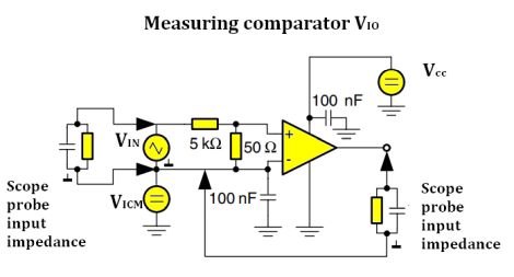
Note that the oscilloscope probes and waveform generator ground are on the inverting input-pin of the comparator.This is why VICM and VCC power supplies must either be floating from earth-ground, or be on an isolation transformer.
Supply voltage varies over a wide range. Inputs must remain within the common-mode operating range. Some bipolar comparators can tolerate 36 V, and these are known as high-voltage comparators. As speed requirements go up, permitted power goes down. That is why some comparators like a middle range of 10 to 15 V while some single-supply CMOS comparators connect to not over 6 V.
Speed is compromised by propagation delay. Because the comparator is essentially a small-signal amplifier, high-frequency gain properties determine the switching speed. Saturation caused by a signal overload slows the circuit. This phenomenon mostly arises from internal capacitance and resistance combining to create substantial time constants. Where the application does not demand speed, high-speed comparators should not be used to avoid aggravating hysteresis problems.
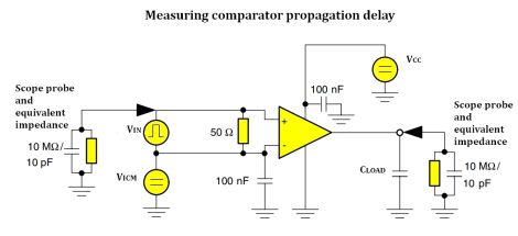
It is possible to measure comparator propagation delay with a scope. One such setup, from comparator maker STM, is shown nearby. One dc supply serves as VCC biasing, a second one as VICM voltage. If the measurement takes place at VICM = 0 V, the source can be removed and the inverting pin directly connected to ground.
To keep low source impedance and prevent from parasitic oscillation during switching, a 100-
nF bypass capacitor sits close to the positive supply pin VCC+ of the comparator.
A second bypass capacitor generally goes to the comparator input pin IIN– when there is a VICM source. A 50-Ω resistor minimizes the effect of input pin capacitance while minimizing signal reflections.
Measurement conditions must be well defined, especially the load capacitance CLOAD which greatly impacts output signal edge speed. Ditto for the TPD value (measured at 50% of VOUT). The CLOAD represents the overall capacitive
loading at the comparator output including loading capacitor, oscilloscope probe capacity
and parasitic capacity of the PCB track.
Note that many pulse generators can’t provide an accurate signal amplitude, especially for low output voltage. Generating a 5 mV overdrive may difficult because such a value is often below the generator accuracy. So for small overdrive measurements, accuracy might improve through use of a 50-Ω attenuator (divider bridge) rather than a single 50-Ω resistor and increase the generator amplitude.
Comparator outputs are close to either zero or to the supply voltage. This is why they can be specified to perform reliably with the TTL or CMOS logic families. A common-emitter output characterizes the bipolar rail-to-rail comparator, so there is a modest voltage drop between the output and the two rails. It equals a saturated transistor’s collector-emitter potential.
Comparators may be push-pull or open drain, depending on their outputs. If the output stage is open drain, an external pull-up resistor is placed at the positive supply, setting the logic-high voltage. In push-pull configurations, there is no pull-up resistor, and current can also be sourced as opposed to the behavior of the open-drain circuit.
The fixed reference voltage source and the input voltage can be applied to either of the comparator’s inputs, and this will determine the positive or negative-going input voltage that is detected. If the inputs are reversed, the output signal will be inverted. A comparator can, accordingly, be connected to operate in either an inverting or non-inverting mode. When the input signal is more negative than the reference signal, the output is logic high. This configuration is known as the negative voltage comparator.
Because signal and reference voltages can be connected to either of the inputs, either an inverting or non-inverting output can be produced. Two opposing comparator configurations can be linked to create what is known as a window comparator circuit. In this implementation, the window comparator looks for inputs that reside within a voltage band, and the output indicates this state. Upper and lower thresholds are created.
Moreover, from the window comparator, it is feasible to build a comparator-based voltage level detector. A voltage divider network makes various voltage inputs for some number of comparators, the output of each connected to a separate LED. The resistances can be chosen so that the comparators and LED’s can detect and display discrete voltage levels.
Comparator output stages operate in their saturated regions so they work well as ADCs, and this is perhaps their most important application, as we see in the digital sampling oscilloscope. Adding positive feedback between output and input overcomes unpredictable behavior.

Leave a Reply
You must be logged in to post a comment.