The Ethernet computer networking protocol is used in local area networks, metropolitan area networks and wide area networks. While the term is often used to distinguish wired data transmissions from Wi-Fi, both use parallel protocol details, notably 48-bit MAC address and Ethernet frame format. Actually, Wi-Fi is Ethernet over a different medium. There are a couple of points about these communication schemes that may be helpful to know when making measurements of their parameters.

Ethernet most commonly uses a twisted-pair cable called Cat 5e (enhanced). The more expensive Cat 6a (augmented) can handle signals at a higher speed. It is worth noting that Cat 6a has a higher twist rate than Cat 5e, which gives it a greater bandwidth.
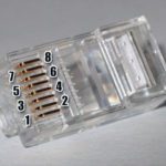
In UTP (unshielded twisted pair) cable containing multiple pairs, each pair has a slightly different twist rate to reduce mutual coupling. In terminating UTP, the twists should be retained as near to the connector as possible.
Ethernet probably owes much of its dominance over other types of communication protocols to the development of first thin coaxial cable and then to the development of UTP, the ubiquitous category cable in use today. UTP is less expensive than coaxial cable and optical fiber. Besides being less expensive and easier to install because there is no shielding, category cable is highly immune to crosstalk, noise and interference, due to twisted pair technology.

The concept of twisted pairs is nothing new. Early telephone engineers used existing telegraph wires, aerial single-wire lines with earth as the return conductor. This worked until the 1880s when electric trams with dc motors and arcing brushes became increasingly common, introducing noise in the telephone circuits. Telephone engineers introduced two-wire balanced circuits, improving the situation substantially. But still, over long hauls, the near wire received more of the unwanted signal than the far wire. To deal with this problem, engineers instituted a method known as wire transposition, where aerial conductors crossed over, reversing positions canceling out the interference. A typical twist rate was six per mile.
Today, twisted-pair lines still employ balanced transmission, that is, neither line is grounded. To realize the benefits of balanced transmission, the circuits driving the balanced lines at the source must themselves be balanced. Balanced lines are less vulnerable to noise and interference, especially when used in conjunction with differential signaling, where common-mode rejection can take place.
Twisted pair depends for its effectiveness on balanced signaling. This is usually implemented in conjunction with differential signaling. The two wires carry equal but opposite signals. The desired information is conveyed by the difference between them, and that is what is detected at the receiver. Any voltage or waveform that is the same in both wires is invisible at the destination. This is known as common mode rejection. If the two wires were run together but not twisted, one of them would receive a greater amount of this objectionable noise or interference than the other, and it would not be rejected. For this to work, the objectionable interfering signal must remain uniform over the distance of a single twist, and that is the rationale for a high twist rate.
A point to note is that the 10 Mbit/sec (10Base-T) and 100 Mbit/sec (100Base-TX) twisted pair Ethernet signals use two-wire pairs for the communications and use differential signaling. Differential signaling is a method for electrically transmitting information using two complementary signals. The technique sends the same electrical signal as a differential pair of signals, each in its own conductor. During a digital pulse, each wire in the pair carries a signal that is the same voltage, but opposite polarity. Differential signaling combined with twisted pair wiring has good noise-canceling capability.
But balanced signals as used on 10Base-T and 100Base-T can’t be viewed accurately by a test instrument that makes a measurement between the instrument input and ground. On a scope, for example, the ground lead on the probes connect to the oscilloscope chassis, which in turn is earth grounded. Consequently, anything connected to the ground lead to will also be connected to earth ground.
(This isn’t a problem when you measure two random points with a battery powered multimeter or scope because the meter is floating, so neither point gets connected to earth ground. So you can measure differences between points without concern for creating a short circuit.)
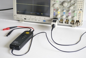
Other than using a battery powered instrument, the most obvious way of examining Ethernet signals on balanced lines is with a differential probe. A differential probe is used to look at signals that are referenced to each other instead of earth ground and to look at small signals in the presence of large dc offsets or other common mode signals such as power line noise.
A differential probe has two inputs, one positive and one negative as well as a separate ground lead. It drives a single terminated 50-Ω cable to transmit its output to one oscilloscope channel. The output signal is proportional to the difference between the voltages appearing at the two inputs.
One problem: Differential probes can be pricey. So there are two other common measurement methods employed when examining Ethernet balanced lines and no differential probe is available. The first assumes the availability of a two-channel scope. The technique is to connect each of the two scope probes to one of the balanced lines, then connect the probe grounds to each other. The scope is set to display the difference between the two inputs (A-B). Signals are around ±2.5 V (over twisted pair) on 10BASE-T and 100BASE-TX uses three-level signals (1 V, 0 V, -1 V).

Another technique uses an old Ethernet card to serve as an interface for the scope input. The idea is to connect the NIC (Network Interface Card) to the Ethernet lines of interest after it has been modified to accept connections to the scope inputs. The modifications are as follows: The NIC contains an Ethernet line transformer that connects to the RJ45 Ethernet connector and to the Ethernet chip on the NIC card. You desolder the Rx and Tx lines coming from the Ethernet chip to the Ethernet line transformer, then substitute coaxial cable connections from the scope inputs on the same pin connections of the line transformer. Generally, these coax cable connections are soldered in.
One difficulty with this idea is that the connections are not technically up to the specifications of an Ethernet line — this circuit creates impedance mismatches which are not good for communications, but usually work well enough if the cable runs are short.
Once Ethernet waveforms are rendered viewable on a scope display, the next step generally involves decoding the transmitted data. Trying to decode Ethernet frames manually generally is impractical, so scopes aimed at professional user incorporate decoding software that will automatically interpret transmissions.

Finally, a few words about WiFi transmissions. WiFi data obeys the Ethernet protocol, so captured WiFi transmissions can be interpreted by the same scope software used to translate Ethernet transmissions. However, if the only parameter of interest is the signal strength of the received WiFi signal, an ordinary smartphone can serve as a simple signal-strength meter. It does so via free apps such as WiFi Analyzer which provide a display of received WiFi signals, their identity, and their level in dB. (Of course, if the need is for a calibrated signal-strength reading in the interests of compliance testing and other stringent demands, you’ll need something more sophisticated.)


Leave a Reply
You must be logged in to post a comment.